105
APPENDIX 3
CAN-BUS DIAGNOSTICS AND TROUBLESHOOTING
1 DISPLAYED ICONS
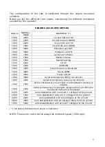
If an icon of the followings appears on the display check as indicated
here below
THIS IS NOT A CAN-BUS ERROR
Check error menu: check from the display into the ERROR
MENU pushing 6 – SERVICE and then 3 – ERRORS, then
skipping the pages it will be showed the devices error status,
where there’s a NO means that the signal from two lines of
that device are not according each other, so check it and
check its connections
Electronic board or software wrong: check if the platform’s
devices are compatibles with installed software, if necessary
contact Hinowa with the serial number and the release
number of the installed software
CAN BUS signal missing: check the connection as indicated at
the step 4 of the present procedure
2
nd
cylinder sensor missing: check the connector of the
position sensor on 3
rd
arm and the sensor itself,
check also the battery charge level, in case of low battery
level let the engine run for some minutes, then check if this
alarm disappears
Battery low level alarm: it could appear especially after the
engine start, check the battery level and eventually charge.
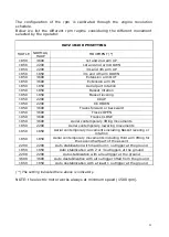
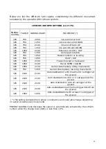
2 CAN TIMEOUT MENU’
As soon as you have CAN BUS error shown on the display, check the
error list on page 4, pushing the buttons 6 – SERVICE
3 – ERRORS
and then pushing 2 times NEXT till page 4 CAN TIMEOUT, the display will
show the following screen on (left side) with the followings meaning
(right side)
Summary of Contents for LightLift 17.75 3S
Page 1: ...1 TECHNICAL COURSE BOOKLET LightLift 17 75 3S LightLift 20 10 3S PERFORMANCE TTPE1720021602 ...
Page 6: ...6 2 2 1 LL17 75 3S PERFORMANCE DIMENSIONS NOTE standard version with 2 persons basket ...
Page 7: ...7 2 2 2 LL17 75 3S PERFORMANCE WORKING AREA 230 KG CAPACITY ...
Page 8: ...8 2 3 1 LL20 10 3S PERFORMANCE DIMENSIONS NOTE standard version with 2 persons basket ...
Page 9: ...9 2 3 2 LL20 10 3S PERFORMANCE WORKING AREA 230 KG CAPACITY ...
Page 43: ...43 HATZ 1B40 EMERGENCY START FOR 17 75 DIESEL ...
Page 44: ...44 PERKINS 402 05 EMERGENCY START FOR 20 10 DIESEL ...
Page 93: ...93 ...
Page 94: ...94 ...
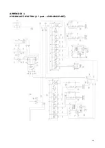
Page 101: ...101 APPENDIX 1 HYDRAULIC SYSTEM 1st part GROUND PART ...
Page 102: ...102 HYDRAULIC SYSTEM 2nd part AERIAL PART ...
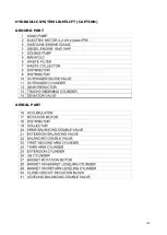
Page 103: ...103 HYDRAULIC SYSTEM LIGHTLIFT CAPTION GROUND PART AERIAL PART ...

