119
-
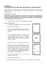
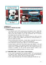
If the display doesn’t start up check the remote control connector and
remote cable, especially CAN BUS wires 5 and 6 (Page E3 wiring
diagram).
-
Check the whole CAN BUS line from ground to platform (Page E3
wiring diagram).
-
Connect remote control at the ground cable and verify its functioning.
If it’s working the problem is on the electric lines to platform basket
cable or on the control position key selector or switches. If also at the
ground remote control is not working there’s a possible problem on
CAN BUS system, check with the CAN BUS troubleshooting (see
appendix 3).
-
If there’s no failure found out on the CAN BUS system, the problem
could be on remote control or on ground master board (ECM1-2).
3)
“JIB ONLY” system doesn’t work:
-
If with machine destabilized on the display doesn’t appear the icon
“JIB ONLY” check that the aerial part is completely close, check also
SERVICE-INPUT signal “POS 3” status (see chapter 11.3) that
indicates the opening of the 3 arm cylinder.
-
If the icon “JIB ONLY” is on display check if there is more than 40 kg
on the basket or the remote control is on the basket (see chapter
5.1.1).
4)
Self-stabilization system doesn’t work:
-
Check alignment icon in the display.
-
Make sure photocells and reflector are clean
-
Make sure alignment is correct on the machine (alignment arrow and
arms completely closed). If alignment icon still OFF check SERVICE-
INPUT signals “FOTO A” and “FOTO B” status (see chapter 11.3).
-
If doing self-stabilization display keeps say “WAIT” close manually the
proportional valves and do the stabilization again. If with the valves
closed it’s working fine you need to put higher CURRENT “STAB
DOWN-sw” using procedure of current setting (see procedure -
Performance parameters setting). If after increasing the current
stabilization is still not working check the valve blocks coil and if there
are ECMs output to the coils (Page M wiring diagram), otherwise
probably there is an hydraulic problem, check one way valves in
hydraulic pumps collector and pressures as indicated in the use and
maintenance manual.
-
If automatic stabilization is not stabilizing machine with proper
leveling (checking bubble level) verify in SERVICE-INPUT signals
“INCLIN X” and “INCLIN Y” (see chapter 11.3). If they are signing the
Summary of Contents for LightLift 17.75 3S
Page 1: ...1 TECHNICAL COURSE BOOKLET LightLift 17 75 3S LightLift 20 10 3S PERFORMANCE TTPE1720021602 ...
Page 6: ...6 2 2 1 LL17 75 3S PERFORMANCE DIMENSIONS NOTE standard version with 2 persons basket ...
Page 7: ...7 2 2 2 LL17 75 3S PERFORMANCE WORKING AREA 230 KG CAPACITY ...
Page 8: ...8 2 3 1 LL20 10 3S PERFORMANCE DIMENSIONS NOTE standard version with 2 persons basket ...
Page 9: ...9 2 3 2 LL20 10 3S PERFORMANCE WORKING AREA 230 KG CAPACITY ...
Page 43: ...43 HATZ 1B40 EMERGENCY START FOR 17 75 DIESEL ...
Page 44: ...44 PERKINS 402 05 EMERGENCY START FOR 20 10 DIESEL ...
Page 93: ...93 ...
Page 94: ...94 ...
Page 101: ...101 APPENDIX 1 HYDRAULIC SYSTEM 1st part GROUND PART ...
Page 102: ...102 HYDRAULIC SYSTEM 2nd part AERIAL PART ...
Page 103: ...103 HYDRAULIC SYSTEM LIGHTLIFT CAPTION GROUND PART AERIAL PART ...


