background image


118 


APPENDIX 9 
FREQUENTLY ISSUES SOLVING 


1)


Dead display 

-


Turn ignition switch  OFF and disconnect the battery cutter. Switch ON 
them  after  a  few  seconds  (first  battery  cutter).  Wait  10  seconds  for 
start  up  and  check  display.  If  you  read  “download”  wait  15  minutes 
and display should start up. If not go ahead. 

-


Check  if  master  board  (ECM1-2)  is  feed  (at  least  one  LED  must  be 
ON).  If  no  lights  check  master  board  (ECM1-2)  feed  and  battery.  If 
there are lights go ahead. 

-


Check remote control connector, remote cable, especially feed on wire 
1 (12V) and ground on wire 7 (Page E3 wiring diagram). 

-


Check that control position key selector is in the proper position 

-


Connect  remote  control  at  the  ground  cable  (see  chapter  11.4)  and 
verify its functioning. If it’s working means that the problem is on the 
electric  lines  to  platform  basket  cable  or  on  the  control  position  key 
selector  or  switches.  If  also  at  the  ground  remote  control  is  not 
working there’s a possible problem on remote control.  
 

2)


 “PREOPERATING” on the remote control display: 

-


If  you  read  “preoperating”  turn  ignition  switch    OFF  and  disconnect 
the battery cutter. Switch ON them after a few seconds (first battery 
cutter). Wait 10 seconds for start up and check display.  

-


If you read “download” wait 15 minutes and display should start up. 

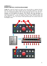
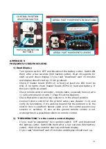
CONTROL POSITION 

SELECTOR SWITCH 

AERIAL PART MOVEMENTS LEVERS 

MOTORS INGNITION 

BUTTONS 

AERIAL PART MOVEMENTS INDICATIONS 

Summary of Contents for LightLift 17.75 3S

Page 1: ...1 TECHNICAL COURSE BOOKLET LightLift 17 75 3S LightLift 20 10 3S PERFORMANCE TTPE1720021602 ...

Page 2: ...4 5 3 STOP BUTTONS 26 5 4 PEDAL OPTIONAL 27 6 EMERGENCY OPERATION 27 6 1 EMERGENCY OPERATIONS OF THE AERIAL PART 29 6 1 1 GRAVITY EMERGENCY DESCENT 29 6 1 2 OPERATIONS FROM GROUND CONTROL POSITION 30 6 1 3 EMERGENCY DESCENT WITH SAFETIES BY PASS 31 6 1 4 EMERGENCY DESCENT WITH HAND PUMP 32 6 2 EMERGENCY MOVEMENTS OF THE GROUND PART 35 6 2 1 TRACK MOVEMENT WITH SAFETIES BY PASS 35 6 2 2 OUTRIGGERS ...

Page 3: ...SPLAY ICONS 71 11 2 ERROR MESSAGES SELF DIAGNOSIS 72 11 3 DIAGNOSTICS ON THE DISPLAY 73 11 4 FUNCTIONING OF THE REMOTE CONTROL ON THE GROUND 81 11 5 LOAD CELL 82 12 POWER SYSTEM 82 12 1 GASOLINE ENGINE HONDA IGX440 83 12 2 DIESEL ENGINE HATZ 1B40 FOR 17 75 DIESEL 89 12 3 DIESEL ENGINE PERKINS 402 05 FOR 20 10 DIESEL 92 12 4 LITHIUM VERSION 48V FOR 17 75 72V FOR 20 10 96 APPENDIX 1 HYDRAULIC SYSTEM...

Page 4: ...ts of numerical part of the LightLift name identify the maximum working height of the machine in meters while the last two digits indicate the maximum outreach in decimeters The aerial platform is equipped with an hydraulic system and an electrical system that interact to ensure safe operating in any situation The two systems are described below the present manual describes also how they interact ...

Page 5: ... 0 89 89 0 89 Max aerial part working inclination 1 1 75 1 1 75 Max slope tolerance 12 15 Petrol version dry weight indicate in CE plate 2190 Kg 2840 Kg Petrol machine operating weight without operator 2230 Kg 2880 Kg Lithium machine operating weight without operator 2300 Kg 2980 Kg Max drive speed with thermic engine with double speed 0 7 1 8 optional 3 6 Km h 0 5 1 3 standard 2 5 Km h Angle of a...

Page 6: ...6 2 2 1 LL17 75 3S PERFORMANCE DIMENSIONS NOTE standard version with 2 persons basket ...

Page 7: ...7 2 2 2 LL17 75 3S PERFORMANCE WORKING AREA 230 KG CAPACITY ...

Page 8: ...8 2 3 1 LL20 10 3S PERFORMANCE DIMENSIONS NOTE standard version with 2 persons basket ...

Page 9: ...9 2 3 2 LL20 10 3S PERFORMANCE WORKING AREA 230 KG CAPACITY ...

Page 10: ...10 2 4 SERIAL NUMBER LOCATION A serial number plate is affixed on to the frame of the machine The following illustrations showing its location SERIAL NUMBER PLATE LOCATION ...

Page 11: ...ncy descent Automatic destabilization selector Left track 1 2 arms Jib Turret rotation Right track Main boom Basket rotation Extension Basket leveling key Electric motor start stop Thermic engine start stop Undercarriage closing Automatic stabilization selector Undercarriage widening Engine speed selector Stabilizers manual operating Service menu selector Display Permission of aerial part operatio...

Page 12: ...attery cutter switch must be active both the stop buttons the first on the remote control and the second on the ground control box must be released and ignition switch on the engine has to be turned ON without start the engine To start the engine press remote control thermic engine button to start the electric motor press electric motor button With cold temperatures with petrol engine it is recomm...

Page 13: ... and the display visualizes the icon PREHEAT PROCEDURE IN PROGRESS While preheating is in progress any movement normally working at 2200 rpm would work at 2200 rpm In case an aerial part movement working at 1500 or 3600 rpm is selected engine changes rpm to 1500 or 3600 and the heating procedure ends In case a track movement working at 1500 or 3600 rpm is selected engine changes rpm to 1500 or 360...

Page 14: ...nd with sensors or actuators installed in the machine The load cell board ECM3 on the jib arm controls the weight in the basket and communicates by CAN BUS with the master board ECM1 2 located in the electric component compartment on the ground part Another board 110 230V BOARD manages the functioning of the electric motor and the charging of the battery when the machine is connected to the 110 23...

Page 15: ...bilized none of the outriggers can touch the ground and the operator must control the machine from ground with remote control in hand the remote control cannot be in the support It is enough to act on the joystick to move the jib If a joystick of another aerial part movement is operated an error message appears on the display JIB ONLY If there are more than 40 Kg weight in the basket or the remote...

Page 16: ...L FOR STABILITY REASON LL17 75 and LL20 10 are provided with a special system that automatically reduces tracks speed or stops the movement in case of stability risks This control depends automatically on different factors Weight in the basket Jib opened or closed Tracks widened or not Slope inclination gradient in axles X and Y OPTIONAL If equipped with double speed drive gear motors the engine r...

Page 17: ...n of 10 seconds will be activate on the display and in the meantime tracks movement is allowed in turtle speed with beeper ON During that by pass the operator can bring machine back to stability condition SPEED CONTROL POSSIBLE CONDITIONS ON THE LL17 75 JIB OPEN Not possible to select HARE X or Y 5 TURTLE Y 7 TURTLE BUZZER Y 13 BUZZER MOVEMENT STOPPED ALARM ICON UNDERCARRIAGE CLOSED X 6 TURTLE BUZ...

Page 18: ...ZZER X 10 BUZZER MOVEMENT STOPPED ALARM ICON UNDERCARRIAGE OPEN X 10 TURTLE BUZZER X 15 BUZZER MOVEMENT STOPPED ALARM ICON Weight inside basket 120 230Kg Not possible to select HARE X or Y 5 TURTLE Y 7 TURTLE BUZZER Y 13 BUZZER MOVEMENT STOPPED ALARM ICON UNDERCARRIAGE CLOSED X 6 TURTLE BUZZER X 10 BUZZER MOVEMENT STOPPED ALARM ICON UNDERCARRIAGE OPEN X 10 TURTLE BUZZER X 15 BUZZER MOVEMENT STOPPE...

Page 19: ...ct HARE X or Y 6 TURTLE Y 13 TURTLE BEEPER Y 20 BASKET DOWNSTREAM OR Y 16 BASKET UPSTREAM BEEPER MOVEMENT STOPPED ALARM ICON UNDERCARRIAGE CLOSED X 8 TURTLE BEEPER X 10 BEEPER MOVEMENT STOPPED ALARM ICON UNDERCARRIGE WIDENED X 10 TURTLE BEEPER X 15 BEEPER MOVEMENT STOPPED ALARM ICON ...

Page 20: ...OPPED ALARM ICON UNDERCARRIAGE OPEN X 10 TURTLE BEEPER X 15 BEEPER MOVEMENT STOPPED ALARM ICON Weight inside basket 120 230Kg Not possible to select HARE X or Y 6 TURTLE Y 10 TURTLE BEEPER Y 15 BEEPER MOVEMENT STOPPED ALARM ICON UNDERCARRIAGE CLOSED X 8 TURTLE BEEPER X 10 BEEPER MOVEMENT STOPPED ALARM ICON UNDERCARRIAGE OPEN X 10 TURTLE BEEPER X 15 BEEPER MOVEMENT STOPPED ALARM ICON Weight inside ...

Page 21: ...ly stabilize and destabilize the machine it is necessary that the aerial part is perfectly closed and aligned and that the relevant icon is visualized in position 6 of the remote control It is then enough to press and hold button 7 of the remote control automatic stabilization and wait for the OK indication on the remote control with remote control in the basket it s necessary also to press the pe...

Page 22: ...ches on the hydraulic part manifold one for the right side and one for the left side When both the outriggers of the same side are at end run the hydraulic oil pressure reaches the maximum value because the max pressure valve releases Consequently the pressure switches informs the ECM1 2 that the position of complete closure of the outrigger s cylinders ERROR SELF STABILIZATION IMPOSSIBLE BECAUSE ...

Page 23: ... outrigger n 3 and in the end outrigger n 4 Pressing again button 2 the icons reappear When one or more outriggers have been positioned in the working zones use the self stabilization to stabilize the machine It is also possible to stabilize the machine using the manual operation of the outriggers but it is faster and safer to always use the automatic stabilization However in case the operator wan...

Page 24: ...he safeties conditions necessary for the aerial part operation have to be respected The basket leveling adjustment function is carried out keeping turned rightwards or leftwards the key switch of the basket leveling on the remote control It is possible to move more than one joystick at the same time however the possibility to carry out two or more functions at the same time may depend on different...

Page 25: ...part AUTOST self stabilization procedure not finished properly see chapter 5 1 2 Self stabilization ROTATE AERIAL PART AND LOWER FIRST ARM Rotate the aerial part and lower the first arm are not always possible as the lower part of the first arm may impact against the engine s carter if the turret is almost completely rotated In practice in order to rotate the turret completely the first arm needs ...

Page 26: ...movement is automatically disabled If the first arm joystick is released and activated again to try to impact the first arm against the engine s carter the movement is automatically disabled and the display will show to the operator the icon to the side indicating that indicating that the first second arm could not be lowered NOTE those controls are not actives using the manual levers on the groun...

Page 27: ...essed again otherwise it s not possible to do any machine movement 6 EMERGENCY OPERATION The machine is designed to allow movements also in emergency situations like mechanical or electrical breakdowns unexpected operator illness etc In all these cases it is always possible to intervene to lower the basket to the ground safely Depending on the movement emergency descent can be carried out from eit...

Page 28: ... as indicated by the picture below REGULATION KNOB only for 17 75 100 CODE 05977600 SAFETIES BY PASS KEY and only for 17 75 100 CONTROL POSITION KEY SELECTOR CODE 1651290015 KEY FOR THE CARTER CONTAINING THE HYDRAULIC VALVE BLOCK FOR THE AERIAL PART CODE 07298800 MAIN CARTER ON THE LEFT SIDE OF THE PLATFORM 17 75 MAIN CARTER ON THE RIGHT SIDE OF THE PLATFORM 20 10 ...

Page 29: ...m functioning properly PROCEDURE Keep pressed button 4 on the remote control for the emergency descent and at the same time use the joystick referring to the arm to close Movements possible with gravity emergency descent are 1st cylinder closure 2nd cylinder closure and jib closure joystick with downward blue arrow Considering this is a gravitational descent it s not possible to lift the arms and ...

Page 30: ...low to choose the aerial part control position Then if all the safety conditions necessary for moving the aerial part are respected the green light near the control position key selector will be ON Once that one of the 2 motors thermic or electric are running it will be possible to control the aerial part using the levers on the valve block as indicated in the picture below NOTE In case the carter...

Page 31: ...ator must keep the key turned during the safeties by pass Then moving the remote control joysticks it is possible to control the aerial part movements As soon as the safeties are by passed the display will show only one icon indicating an opened padlock for few seconds This icon will appear in position 7 of the display while in position 5 will appear the icon machine stabilized ATTENTION To by pas...

Page 32: ...ements It is absolutely prohibited to make different operations than the ones specified above like open the extension arm lift the jib move the outriggers and in general any operation that may compromise the stability of the machine To carry out emergency descent under the conditions described above follow the procedure below In case of the aerial part proportional valve is screw type please follo...

Page 33: ...om the main carter and insert it in the specific adjustment screw of the proportional valve c Screw in the knob completely d Shift the deviator on the manual pump into the position for aerial part movement by following the indications on the label located near the pump picture below HAND PUMP MOVEMENT SCREW PROPORTIONAL VALVE REGULATION KNOB ON 17 75 ON 20 10 ...

Page 34: ...er closure f After the descent operation unscrew completely the proportional valve remove the knob and replace it in its original position PROCEDURE B AERIAL PART FOR BUTTON TYPE PROPORTIONAL VALVE ON 17 75 FROM 200 AND 20 10 a Turn OFF the ignition switch b Shift the deviator on the manual pump into the position for aerial part movement by following the indications on the label located near the p...

Page 35: ...use the ground emergency procedure is to close the outrigger and displace the platform to clear an area or load the platform on a truck trailer 6 2 1 TRACK MOVEMENT WITH SAFETIES BY PASS SITUATIONS FOR USE IT Breakdown of an outrigger micro switch an outrigger micro switch is out of order and the signal is closed even if the outrigger is not touching the ground In this case tracks are not moving T...

Page 36: ...has been reached The safeties by pass of the undercarriage enables only tracks movements for safety reason it is not possible to move the outrigger cylinders NOTE In order to fulfill this emergency operation the proper key is located as indicated in chapter 6 6 2 2 OUTRIGGERS MOVEMENT WITH THE MANUAL PUMP SITUATIONS FOR USE IT Engine and or electric motor not working for engine emergency start see...

Page 37: ...mpletely closed and aligned b Fully but delicately tighten the black handles of the proportional valves located on the two valve blocks of the undercarriage SCREW PROPORTIONAL LEFT UNDERCARRIAGE SCREW PROPORTIONAL RIGHT UNDERCARRIAGE SCREW TYPE PROPORTIONAL VALVE FOR GROUND PART BUTTON TYPE PROPORTIONAL VALVE FOR GROUND PART ...

Page 38: ...riage right part deviator using the black cap in the picture below in order to send oil to the right ground part d Use the levers of the right undercarriage valve block to activate the desired movement while using the hand pump to send oil to the movement see picture AERIAL PART UNDERCARRIAGE RIGHT PART DEVIATOR HAND PUMP DEVIATOR ON 17 75 ON 20 10 ON 17 75 ON 20 10 ...

Page 39: ...iator and unscrew the screw proportional valves of the undercarriage valve blocks PROCEDURE D GROUND PART BUTTON TYPE PROPORTIONAL VALVE ON 17 75 FROM SERIAL NUMBER 013L7 AND 20 10 a Check that the platform is completely closed and aligned b In order to move the right side of the undercarriage move the deviator of the hand pump in the corresponding position than manually screw the aerial part unde...

Page 40: ...ght side to move outrigger 3 and 4 d Use the levers of the right undercarriage valve block to activate the desired movement while the proportional valve button is pressed at the same time use the hand pump to send oil to the movement see picture BUTTON PROPORTIONAL LEFT UNDERCARRIAGE BUTTON PROPORTIONAL RIGHT UNDERCARRIAGE AERIAL PART UNDERCARRIAGE RIGHT PART DEVIATOR HAND PUMP DEVIATOR ON 17 75 O...

Page 41: ... position f Use the levers of the left undercarriage valve block to activate the desired movement while the proportional valve button is pressed at the same time hand pump have to be used to send oil to the movement see picture below ON 17 75 ON 20 10 HAND PUMP DEVIATOR ON 17 75 ON 20 10 ON 17 75 ON 20 10 ...

Page 42: ...ws how to separate engine from the platform system It could be useful in the followings cases To verify if the engine is out of order To handle manually the machine s hydraulics by the proportional valves and or deviator as showed in chapter 6 1 4 and 6 2 2 as indicated by the previous procedures but using the engine instead of the hand pump HONDA iG440 EMERGENCY START ...

Page 43: ...43 HATZ 1B40 EMERGENCY START FOR 17 75 DIESEL ...

Page 44: ...44 PERKINS 402 05 EMERGENCY START FOR 20 10 DIESEL ...

Page 45: ...YSTEM LL 17 75 3S AND 20 10 3S PERFORMANCE FROM LL17 75 4 and LL20 10 3 read APPENDIX 9 7 1 COMPONENTS LOCATION AERIAL PART VALVE BLOCK GROUND PART VALVE BLOCKS HYDRAULIC COLLECTOR ON 20 10 HYDRAULIC COLLECTOR ON 17 75 ...

Page 46: ... output line to select which one of the two lines should be fed with oil The outlet lines of the pump units are conveyed through a manifold 5 into two main outlet tubes A and B Six one way valves avoid that oil under pressure returns to the tank through an unused pump unit B line sends oil under pressure to the left hand undercarriage valve block 8 A line sends oil under pressure to the deviator v...

Page 47: ...e deviator coil is energized when with engine or electric motor running all outriggers are touching the ground but remote control is not placed on its support SECOND SPEED CONTROL AND AUTO2SPEED OPTIONALS On 17 75 second speed is optional where installed is equipped with auto2 speed On 20 10 second speed is standard SECOND SPEED BLOCK TO THE LEFT VALVE BLOCK TO THE 2ND SPEED ACTIVATION DRAINAGE TO...

Page 48: ...eases because a greater driving force is required the maximum pressure valve will allow the automatic reduction of the gear and then of the tracks speed Auto2speed system 7 2 GROUND PART FUNCTIONING The functioning of the ground part is limited by the conditions listed here below It s possible to move the outriggers only when the machine is closed and aligned i e when the photocells receive the si...

Page 49: ...rated at 165 bar Oil from line A when the coil of the deviator valve 14 is energized by the control module is sent to the right side hydraulic undercarriage valve block 9 Here it commands the two right side outriggers and the hydraulic drive gear motor for right track through a proportional valve managed by the control module and ON OFF solenoid valves one per movement The deviator valve is not fe...

Page 50: ...he forward or backward movement is activated the brake is deactivated through oil under pressure and is managed by an unidirectional valve with two lines For drive gear motors functioning the engine is set at maximum speed with the selector in position N on the remote control and minimum speed with the selector in the TURTLE position If the platform is equipped with the double speed drive gear mot...

Page 51: ...set at maximum speed with the selector in position N on the remote control and minimum speed with the selector in the TURTLE position 7 3 AERIAL PART FUNCTIONING A line is connected to a deviator valve 14 When the control module allows movement of the aerial part it does not energize the deviator valve 14 which diverts oil flow toward the aerial part valve block 18 This condition is signaled to th...

Page 52: ...in the aerial part valve block The cylinder for the 1st and 2nd arms 23 the cylinder for the 3rd arm 24 and the jib cylinder 26 are equipped two double piloted balance valves and a solenoid valve for gravity emergency descent The 3rd arm cylinder 24 has also an internal sensor for the piston position The piloted balance valves also carried out the function of a block and anti shock valve The solen...

Page 53: ...ed by a double piloted balance valve There are also two anti cavitation valves that prevent the intake of air if the operator acts on the basket leveling thereby varying the balance between the stroke of the moving cylinder and the exhaust cylinder FIRST AND SECOND ARM FUNCTIONING The first and second arms are moved by only one cylinder that is controlled directly by the aerial part valve block Th...

Page 54: ... working with the third arm the basket is leveled hydraulically using two cylinders with chambers connected in parallel The first with the moving function is located on the connecting arm of the third arm while the second is located under the basket and functions as an exhaust cylinder Oil pushed from the first cylinder through the movement of the third arm is sent to the second cylinder which is ...

Page 55: ...useful in case of technical assistance 8 1 CAN BUS SYSTEM The electrical system works with a CAN BUS system where CAN Controller Area Network BUS is the channels for peripherals This is essentially a communication system among different electronic control units in the machine They interact with each other and with sensors and actuators located on the platform The CAN communication protocol is stan...

Page 56: ...ARD positioned inside the remote control CAN BUS system is composed also by the other components here below detailed Inside the main carter at the base of the platform aside the ECM1 2 or fixed on the box cover is also located the MODEM as indicated in the picture below For 17 75 from 200 and for 20 10 inside the same main carter fixed on the box cover aside the MODEM is also located the ENGINE RE...

Page 57: ...ed in the box on the connecting arm between the 2nd and 3rd arms 2nd ARM BOX SCHEDULE Only for 17 75 100 inside the jib arm box where is installed the ECM3 is also located the JIB CONNECTOR SCHEDULE as indicated in the picture below JIB CONNECTOR SCHEDULE ONLY FOR 17 75 100 2nd ARM BOX SCHEDULE ONLY FOR 17 75 100 ...

Page 58: ...ER BOARD ECM1 2 2nd ARM BOX SCHEDULE JIB CONNECTOR SCHEDULE 8 2 CAN BUS DEVICES CONNECTION SCHEME ONLY FOR 17 75 100 CAN BUS system connections LOAD CELL BOARD ECM3 3rd ARM CYLINDER SENSOR MODEM REMOTE CONTROL ...

Page 59: ...Tracks widening sensor switches they are 2 sensors installed on the cylinders that detect their position enabling ECM1 2 to know the tracks widening position and allowing the AUTOMATIC SPEED CONTROL function b Rotation proximity sensor on the ball bearing ring it s a detector of the ball bearing ring position that enables the ECM1 2 to know the position of the machine turret and to prevent contact...

Page 60: ...ble control line normally closed The electric signal enters in the ECM1 2 f Accelerometers welded on the ECM1 2 they detect the inclination of the machine on the ground in order to allow the movement of the aerial part or not The inclination tolerance is 1 on both axes g Photocells when they receive the signal by the reflector machine closed and aligned they close the line and send a signal to the...

Page 61: ...ngle signal and it communicates with the ECM1 2 k Emergency button on the ground it s a double signal button that communicate to the ECM1 2 l Emergency securities by pass it s a double ways safeties bypass key switch with double switches each way that communicate with the ECM1 2 The key need to be kept turned otherwise it will return to central position m Pressure sensors they are two pressure sen...

Page 62: ...62 8 4 SAFETY DEVICES NOT IN CAN BUS CONNECTION SCHEME CAN BUS LINES ECM1 2 ECM3 ONLY ON 20 10 ...

Page 63: ... 1 ECM2 MASTER BOARD FRONT MODULE LED CODE With LED steady ON DL1 green LED ON Power 5V to MASTER BOARD FRONT MODULE CPU DL2 yellow LED ON All the outriggers are lifted from the ground or machine is closed and aligned photocells signal DL3 yellow LED ON All the outriggers are touching the ground or all the outriggers are lifted from the ground DL1 DL2 DL3 ...

Page 64: ...DL4 green LED ON power 5V to safety channel B CPU DL5 yellow LED ON safety relay for tracks functions channel B CPU closed DL6 yellow LED ON safety relay for aerial functions channel B CPU closed 8 5 3 ECM3 LOAD CELL BOARD LED CODE DL1 DL3 and DL2 DL4 blinking green red load cell board not calibrated DL1 DL2 green LED steady ON from LL17 4 and LL20 3 only green LED blinking load cell board calibra...

Page 65: ...ed battery in maintaining DL3 green LED steady ON 12V feeding from the electronic transformer switching ON DL3 green LED flashing current required is too high it could be due to battery level too low 8 5 5 MODEM LED CODE DL1 green LED steady ON power ON DL2 blue LED flashing each 1 seconds Net signal searching DL2 blue LED flashing each 3 seconds Line ready DL1 DL2 DL1 DL3 DL2 ...

Page 66: ...normally uploaded on the master board ECM1 2 To fulfill the electronic boards software uploading on the master board ECM1 2 by CAN BUS it s necessary to have installed on the laptop the software RamHino starting from 5 0 version To connect the laptop to the machine is necessary the optional connection kit and to follow the specific procedure The necessary connection kit is composed by Peak tool an...

Page 67: ...d go to the last page called Software Uploader For any further details look at the RamHino training brochure 9 2 ELECTRONIC BOARDS SOFTWARE INSTALLATION In case the master board ECM1 2 has been replaced it s necessary to install its software with the software RamHino starting from 5 0 version In case the load cell board ECM3 or the modem have been replaced they need to be activated installing the ...

Page 68: ...ng from the list SAFETY A SAFETY B WEIGHT A WEIGHT B and MODEM it is so possible to install that software 9 3 ELECTRONIC BOARDS SOFTWARE UPDATING In case of on the master board ECM1 2 has been uploaded an updated software release for master board ECM1 2 itself or for whatever electronic board different from the current software release on the remote control display right down corner it is visualiz...

Page 69: ...ead APPENDIX 9 After replacing the load cell board or the load cell sensor on the platform it s necessary to calibrate the load cell board This procedure is described in details in appendix 5 NOTE Weight system calibration procedure even if basket maximum capacity is 230 Kg requires a 200 Kg max load setting then the system automatically gets the 230 Kg limit Therefore to calibrate the system it m...

Page 70: ...output Voltage from the electronic transformer doesn t depend on the electric network Voltage or frequency output is calibrated by Hinowa at 12 7 V DC On the lower side of the electronic transformer there s a green LED that is lighted when the electronic transformer is active The output Voltage DC can be check measuring the Voltage between the two pins here below indicated while the green connecto...

Page 71: ... 11 REMOTE CONTROL The general functions of the remote control and its use are illustrated in Chapters 3 4 5 and 6 of this booklet The remote control contains the interactive display with self diagnosis signaling of breakdowns and operational suggestions 11 1 DISPLAY ICONS The display indicates the status of the machine and the operating mode selected A list of all possible icons that may appear o...

Page 72: ...bed in chapter 5 2 Overload in basket Press pedal option Safety by pass active Gravity emergency descent Select a control Battery voltage low Weigh in basket too low Engine preheating active Lift 1 and 2 arms Inclination too high to stabilize machine Remove weight or remote control from basket Inclination too high to drive safely Automatic periodical service reminder Jib only possible movement Con...

Page 73: ...hat modify the calibrations and safety devices of the machine Pressing button 9 allows access to the SERVICE menu followed by a list of 9 alternatives that are detailed below ERROR ERROR ERROR NO Close and allign the machine Overload in basket A stop button is pressed Error in sensor on 3 arm cylinder Movement not allowed by gravity emergency descent JIB ONLY ERROR It is possible to move only the ...

Page 74: ...switch is released and A line is closed OFF Outrigger n 1 lifted the switch is pressed and A line is opened ST1 GND B ON Outrigger n 1 on the ground the switch is released and B line is closed OFF Outrigger n 1 lifted the switch is pressed and B line is opened FREE A1 ON DO NOT CONSIDER OFF DO NOT CONSIDER FREE B1 ON DO NOT CONSIDER OFF DO NOT CONSIDER ST2 GND A ON Outrigger n 2 on the ground the ...

Page 75: ...e activated normal working condition line B of the ground part safeties by pass is opened EM GRND A ON Stop button on the ground is released A line of the stop button is closed OFF Stop button on the ground is pressed A line of the stop button is opened EM GRND B ON Stop button on the ground is released B line of the stop button is closed OFF Stop button on the ground is pressed B line of the stop...

Page 76: ...es on extension is pressed and the line is open emergency condition START M TE ON The ground button for engine start is pressed OFF The ground button for engine start is released MOTOR TEMP To consider only for LL20 10 ON The engine reached the max functioning temperature emergency condition the engine remains at min OFF The engine maintains the correct functioning temperature normal working condi...

Page 77: ...n the support in basket INCLIN X 0 Indicates the inclination of the machine on the X axis in tenth of degrees accelerometer A 0 Indicates the inclination of the machine on the X axis in tenth of degrees accel B INCLIN Y 0 Indicates the inclination of the machine on the Y axis in tenth of degrees accelerometer A 0 Indicates the inclination of the machine on the Y axis in tenth of degrees accel B LO...

Page 78: ...his list refer to devices with 2 safety lines where the signals of the two lines are not coherent Once entered in the menu it is possible to visualize 5 different pages selecting them through buttons 1 and 2 it is always possible to exit from the errors menu selecting button 9 As already mentioned the errors menu underlines only the discordance between the two lines A and B of the same control the...

Page 79: ...round FREE DO NOT CONSIDER ESSICAE Safeties bypass key switch for aerial part safeties by pass ESSICCA Safeties bypass key switch for ground part safeties by pass EM GROUND Stop button switch on the ground PHOTO Photocells Indicates if the photocells have the same signal ALL TEMP Option reserved for some markets External temperature sensor MICROJIB Control switch if the jib arm is perfectly closed...

Page 80: ...side at this point it is enough to move joystick n 1 to check the functioning Press buttons 1 and 2 to visualize the desired joystick The indication has to be 0 with released joystick while it has to be circa 127 with joystick at end run both forward and backward The value growth has to be proportional to the movement of the joystick SAFETY Safety lines REMOTE Remote control CIL1 2 Do not consider...

Page 81: ...e ground remote control if the operator is in the basket except for emergency reasons To connect the remote control on the ground please follow the instructions below 1 Make sure that the ignition switch is turned OFF and on that the remote control display without there isn t any indication 2 Disconnect the remote control from the cable on the basket and screw the jumper connector on the same cabl...

Page 82: ... double signal to the ECM3 The ECM3 located on the jib arm elaborates and compares the double signal to verify that both the lines indicate the same value within a certain tolerance If this condition is respected and if the load is less than the maximum allowed CE 230 kg ANSI 500 lbs the ECM3 communicates the information to the master board ECM1 2 through CAN BUS line Otherwise in case of overchar...

Page 83: ...ption 328 g KW h Compression ratio 8 1 1 Lubricating system Forced splash type Oil capacity 1 10 l Starting system Recoil and starter motor Stopping system Ignition primary circuit open Carburetor Horizontal type butterfly valve Air cleaner Dual element type Governor STR self turning regulator governor The ECM1 2 is interfaced with an electronic unit applied on the Honda engine carburetor which th...

Page 84: ...500 2200 3rs and 4th arm UP 1500 1500 3rs and 4th arm DOWN 1500 3600 Extension arm OUT 1500 3600 Extension arm IN 1500 1500 Aerial part rotation 1500 1500 Basket rotation 1500 1500 Basket leveling 1500 2200 Jib UP 1500 2200 Jib DOWN 1500 3600 Tracks forward or backward 1500 3600 Tracks OPEN 1500 3600 Tracks CLOSE 1500 3600 Aerial contemporary lifting movements 1500 2200 Aerial contemporary lowerin...

Page 85: ...ast 1 outrigger at the ground The setting indicated here above is indicatory NOTE the electric motor works always at minimum speed 1500 rpm SERIAL NUMBER LOCATION The serial number is stamped on the cylinder barrel Refer to this when ordering parts or making technical inquiries TROUBLESHOOTING SELF DIAGNOSIS AS INDICATED BY THE LED When the battery is disconnected self diagnosis with the LED is no...

Page 86: ...ngine continues to run Wire harness connecting engine temperature sensor and Engine control unit failure At start up Engine does not start Engine control unit failure 6 flashes Power coil failure While engine is running Engine stops Wire harness connecting power coil failure and Engine control unit failure At start up Engine does not start Engine control unit failure 8 flashes Program failure Whil...

Page 87: ...ine is stopped the engine does not start until the faulty engine temperature sensor is solved FIRST OPERATION Check fueling from fuel tank to carburetor Fuel filter replacement Lose drain screw Let fuel drain Pull recoil 3 or 4 times Check fuel coming from fuel tank If fuel is not coming from fuel tank proceed to replace fuel filter in fuel tank ...

Page 88: ...88 SECOND OPERATION IF PROBLEM IS ON ENGINE Spark checking Changing the engine control unit Changing the ECU ...

Page 89: ...mption at full load Direction of rotation power take off end Anti clockwise Valve clearance 10 30C 0 10 mm Weight incl fuel tank air cleaner exhaust silencer recoil starter and electric starter Approx 55 Kg TYPE PLATE The type plate is placed on the noise crankcase insulating hood and includes the following engine information 1 engine type 2 code only for special equipment 3 engine number also sta...

Page 90: ... the rpm and communicates them to the ECM1 2 The ECM1 2 according to the rpm information received from the sensor and according to the movement selected by the operator controls a solenoid that regulates the rpm RPM SENSOR SOLENOIDE FOR RPM CONTROL ...

Page 91: ...3600 Tracks OPEN 1850 3600 Tracks CLOSE 1850 3600 Aerial contemporary lifting movements 1850 2200 Aerial contemporary lowering movements 1850 1850 Aerial contemporary movements including Basket leveling or rotation 1850 1850 Aerial contemporary movements including third arm lifting for the second half part of the ascent 2200 2200 Auto stabilization with maximum 1 outrigger at the ground 1850 1850 ...

Page 92: ...angement In Line two cylinder Displacement 507 cm Bore Stroke 67 72 mm Fuel tank capacity 10 l Compression Ratio 23 5 1 Rotation that is viewed from the flywheel Counterclockwise Maximum Operating speed rpm 3600 rpm Firing Order 01 feb Valve Lash Setting Inlet 0 20 mm 0 008 inch Valve Lash Setting Exhaust 0 20 mm 0 008 inch ...

Page 93: ...93 ...

Page 94: ...94 ...

Page 95: ...0 3600 Tracks OPEN 1500 3600 Tracks CLOSE 1500 3600 Aerial contemporary lifting movements 1500 2200 Aerial contemporary lowering movements 1500 1500 Aerial contemporary movements including Basket leveling or rotation 1500 1500 Aerial contemporary movements including third arm lifting for the second half part of the ascent 2200 2200 Auto stabilization with maximum 1 outrigger at the ground 1500 150...

Page 96: ...s ANSI 13 Amps Operating temperature range from 20 to 50 C Efficiency 90 Type of protection IP65 Battery charger codes 48 Volt battery charger Led Light Meaning Red 1st charge step maximum current possible to the cells Red Flashing 2nd charge step Cells under charge with reduced current Yellow 3rd charge step Cells under light charge Yellow flash 4th charge step Balancing and maintaining Green Red...

Page 97: ...y charger In the Lithium system specific training are listed with the meanings of the fault codes of the individual devices The here above image represent the 48V battery pack For further details about lithium system consult the specific manual The configuration of the rpm is calibrated through the inverter system If the inverter is replaced a new parameterization is required LiFePo4 BATTERIES INV...

Page 98: ...2 communicates with the inverter controlling three contacts through which predetermined rpm are set In the specific instance the contacts are the followings FOR 48 V BATTERY PACK LL17 75 FOR 72 V BATTERY PACK LL20 10 ...

Page 99: ...cks OPEN CLOSE 325 1050 2100 Aerial contemporary lifting movements 325 750 1350 Aerial contemporary lowering movements 325 2100 2100 Auto stabilization with maximum 1 outrigger at the ground 325 2100 2100 Auto stabilization with 2 or 3 outriggers at the ground 325 2100 2100 Auto stabilization with all outrigger at the ground 325 2100 2100 Auto destabilization with all outrigger lifted from the gro...

Page 100: ...racks OPEN CLOSE 450 1200 2550 Aerial contemporary lifting movements 450 900 1500 Aerial contemporary lifting movements 450 1800 1800 Auto stabilization with maximum 1 outrigger at the ground 450 1800 1800 Auto stabilization with 2 or 3 outriggers at the ground 450 1800 1800 Auto stabilization with all outrigger at the ground 450 1800 1800 Auto destabilization with all outrigger lifted from the gr...

Page 101: ...101 APPENDIX 1 HYDRAULIC SYSTEM 1st part GROUND PART ...

Page 102: ...102 HYDRAULIC SYSTEM 2nd part AERIAL PART ...

Page 103: ...103 HYDRAULIC SYSTEM LIGHTLIFT CAPTION GROUND PART AERIAL PART ...

Page 104: ... right side of the keyboard together with the top outermost button on the left for 7 seconds On the display will appear JOY TEACH and the instruction to calibrate the joystick To do this move each joystick completely down and then completely up To end the TEACH IN mode centre all the joystick and press button 7 once The remote control switches back into normal mode and the display clears ...

Page 105: ...with the serial number and the release number of the installed software CAN BUS signal missing check the connection as indicated at the step 4 of the present procedure 2nd cylinder sensor missing check the connector of the position sensor on 3rd arm and the sensor itself check also the battery charge level in case of low battery level let the engine run for some minutes then check if this alarm di...

Page 106: ...devices and connections check that requires the following schematics CAN BUS DEVICES CONNECTIONS here below CAN BUS DEVICES POSITION here below CAN NETWORK page E3 of the electric wiring diagram MODEM DISCONNETION CHECK Disconnecting the modem machine should work as well if the CAN BUS problems will disappear once the modem is disconnected it will means that we have found the cause CONNECTIONS CHE...

Page 107: ...n with battery cutter disconnected connect two external wires red lines here below between ECM1 2 and ECM3 disconnecting the original wires on this tract then check the status if with this configuration the error doesn t disappear means that the failure is on a device otherwise if the error disappears it means that the failure was in the original connections it could be possible that it appears SE...

Page 108: ...ER BOARD ECM1 2 2nd ARM BOX SCHEDULE JIB CONNECTOR SCHEDULE CAN BUS DEVICES CONNECTIONS BLUE LINES ONLY FOR 17 75 100 CAN BUS system connections LOAD CELL BOARD ECM3 3rd ARM CYLINDER SENSOR MODEM REMOTE CONTROL ...

Page 109: ...109 ENGINE REVOLUTION SCHEDULE SCHEDULE MASTER BOARD ECM1 2 FOR 17 75 FROM 200 AND 20 10 CAN BUS system connections LOAD CELL BOARD ECM3 3rd ARM CYLINDER SENSOR MODEM REMOTE CONTROL ...

Page 110: ...ave already changed more than one spares of the same device in this case the problem could be caused for example by water going inside the box so take a look to possible traces of oxidation on the contacts in this case isolate better the box Be careful that the jib box cover has a direction to be assembled if assembled in the wrong direction water goes inside FOR 17 75 FROM 200 AND 20 10 ONLY FOR ...

Page 111: ...here below check the remote control receiver and ECM1 2 CAN BUS resistances in the red round on page CAN NETWORK page E i e test the resistance measured within the cable H and L that should be about 120 Ohm with the device disconnected from the other and 60 Ohm with the device connected each other always with FEED OFF ...

Page 112: ...efines the movement speed and must be settled taking care of the law limit achieving a safe and smooth handling of the platform There is a limit flow rate of the proportional valve that even increasing the current setting could not be overcome The minimal current is the value given to the proportional valve when the movement begins CURRENTS SETTING The currents of each movement could be red into t...

Page 113: ... the platform The deceleration ramp defines the delay between the joystick release and the stop of the movement therefore has to be settled in order to achieve a safe and comfortable handling of the platform RAMPS SETTING The ramps setting of each movement could be red into the ramp menu pressing button 6 SERVICE 4 RAMP and then pressing button 1 and 2 to scroll the different movement To set the r...

Page 114: ...PROCEDURE FROM LL17 75 4 and LL20 10 3 read APPENDIX 9 This operation is required when the load cell has lost the references for the maximum loads or null loads this may be due to voltage surges that have damaged the load cell board ECM3 This events is very infrequent for construction the load cell board ECM3 must absolutely keep the programming parameters except in case of external factors The ca...

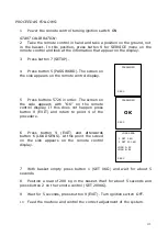
Page 115: ...ears with OK on the remote control display If this does not happen press button 9 EXIT and return to point 4 of the procedure 6 Press button 9 EXIT and afterwards button 6 LOAD SENS At this point the screed on the side appears on the remote control display 7 With basket empty press button 1 SET 0KG and wait for about 5 seconds 8 Position a load of 200 kg in the basket Wait for about 5 seconds and ...

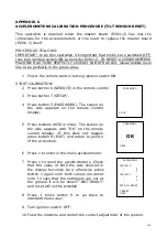
Page 116: ...ess button 5 PASSWORD The screen on the side appears on the remote control display 5 Press buttons 4658 in order The screen on the side appears with OK on the remote control display If this does not happen press button 9 EXIT and return to point 4 of the procedure 6 Press 1 to enter in the menu accelerometer 7 Press 1 to reset the accelerometers Check that the value of both the axle showed in the ...

Page 117: ... to aerial part System switched ON with machine stabilized Deviator to aerial part System switched ON with machine not stabilized Deviator to ground part APPENDIX 8 REMOTE CONTROL STOP BUTTON BY PASS With machine stabilized while remote control is connected to its basket connector with stop button pressed in case of an emergency it s possible to by pass it keeping turned rightward the control posi...

Page 118: ...osition key selector is in the proper position Connect remote control at the ground cable see chapter 11 4 and verify its functioning If it s working means that the problem is on the electric lines to platform basket cable or on the control position key selector or switches If also at the ground remote control is not working there s a possible problem on remote control 2 PREOPERATING on the remote...

Page 119: ...f there is more than 40 kg on the basket or the remote control is on the basket see chapter 5 1 1 4 Self stabilization system doesn t work Check alignment icon in the display Make sure photocells and reflector are clean Make sure alignment is correct on the machine alignment arrow and arms completely closed If alignment icon still OFF check SERVICE INPUT signals FOTO A and FOTO B status see chapte...

Page 120: ... appears on the display or the error list see chapter 5 2 and identify where the problem is 7 HELP ERROR alarm visualized on the display Press SERVICE button Press button 3 for ERRORS see chapter 11 3 Verify the error self diagnosis 8 STOP icon visualized on the display Verify the stop buttons status must be both released Verify in the SERVICE INPUT menu the signals EM BASK and EM GRND are ON if o...

Page 121: ...gnals need to be over 50 to had a good connection BER 0 100 network line signals 12 Thermic engine not starting Check display and eventual STOP icon Check proportional valves are unscrewed Check Honda engine ECM diagnosis with flashing code see chapter 12 Check engine fuses and wires connectors Check hydraulic oil filter air filter gasoline or diesel filter in case also the sediment cup as indicat...

Page 122: ...thium pack the main key is on ground control box NEW AERIAL PART HYDRAULIC VALVEBLOCK AND NEW CONTROL POSITION KEY SELECTOR BOX Inside the ground control box the aerial part hydraulic valveblock has been changed the new one works without any accumulator and its proportional valve is controlled by a red lever Aside the aerial part hydraulic valveblock the new control position key selector box is ma...

Page 123: ...activation Electric motor is equipped with a disengager NEW CHARGING SYSTEM The electronic transformer has been changed the new one is installed without box inside the carter aside the 12V battery so that transformer box is not anymore installed New electronic transformer has a fixed output tension of 14 Volt DC not depending on the electric network tension or frequency its output current is autom...

Page 124: ...logy with capacity 60Ah NEW LOAD CELL SYSTEM Load cell sensor and load cell board ECM3 are different from the one installed till LL17 75 300 and LL20 10 200 New parts code are Load cell sensor from LL17 75 400 and LL20 10 300 part code 17669800 Load cell board from LL17 75 400 and LL20 10 300 part code 17770300 With new load cell system calibration procedure consist only in 0 Kg calibration not 20...

Page 125: ...ment 389 cm3 Bore per Stroke 88 64 mm Cooling system forced air Net power 8 7 kW at 3600 rpm Continuous net power 7 0 kW at 3600 rpm Maximum net torque 26 4 N m at 2500 rpm Fuel consumption at continuous net power 3 5 L h at 3600 rpm Compression ratio 8 2 1 Lubricating system butterfly valve type Oil capacity 1 1 l Starting system Recoil and starter motor Stopping system Ignition primary circuit o...

Page 126: ...r backward 1500 3500 Tracks OPEN 1500 3500 Tracks CLOSE 1500 3500 Aerial contemporary lifting movements 1500 2350 Aerial contemporary lowering movements 1500 1500 Aerial contemporary movements including Basket leveling or rotation 1500 1500 Aerial contemporary movements including third arm lifting for the second half part of the ascent 2350 2350 Auto stabilization with maximum 1 outrigger at the g...

Page 127: ...trigger warning lights are bigger than old version and led NEW BASKET WITH NEW REMOTE CONTROL SUPPORT AND WHEELS New basket is equipped with a new design remote control support and with four wheels to be better displaced when removed ...

Page 128: ...tance if the operator press the SkyGuard bar while he was opening the telescope the machine will automatically close the telescope for a certain time and then stop In order to allowed again the aerial part movements it s necessary to press and release after a few seconds the remote control emergency stop When it s installed and activated if SkyGuard bar is kept pressed for a while when tracks or o...

Page 129: ...ssed by keeping pressed the button n 8 of the remote control this operation allows to move the machine only in the case to have the bar always pressed or stuck but it will not allow the movements if the bar has been pressed and released NOTE Skyguard could be activated or deactivated with the relevant password by the MENU OPTIONAL SKYGUARD ...

Reviews: