10
STEP 8.
Attaching Roller Supports
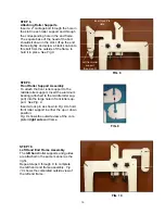
Insert a 2” carriage bolt through the hole in
the slot in each roller support and through
the corresponding hole in the end frame.
The square base of the head of the bolt
should sit down in the slot. Lift up the end
frame slightly and screw a black knob onto
this bolt from the outside of the frame to
hold it in place.
See Fig 8.
STEP 9.
Front Roller Support Assembly
To attach the front roller support to the
middle roller support. Insert the aluminum
bearing (attached to the middle roller sup-
port) into the large hole in front roller sup-
port.
See Fig. 9.
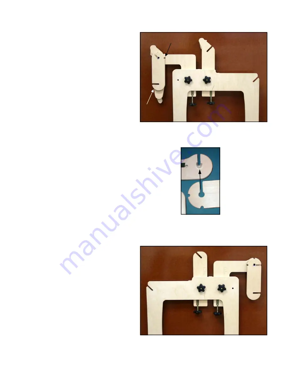
Insert a lock pin as shown in
Fig. 8
to hold
front roller support in either the up or down
position.
Fig. 8
shows the outside view of the com-
pleted
right side
end frame.
FIG. 9
STEP 10.
Left Hand End Frame Assembly
The
left hand
roller supports and guides
are attached in the same manner as the
right.
Repeat steps 3 through 9 to complete
the left hand end frame assembly.
Fig
10
shows the completed outside view of
the left end frame.
FIG. 8
Insert Lock Pin
Here
Left front roller
support
(See step 9)
FIG. 10


