background image

25

_____________________________________________________________________

Chapter 5Maintenance and Service

______________________________________________________________

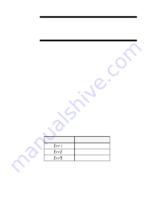
Error message

Meaning

ROM error

RAM error

Adjustment data error

Chapter 5

Maintenance and Service

Cleaning

To clean the product, wipe it gently with a soft cloth
moistened with water or mild detergent. Never use solvents
such as benzene, alcohol, acetone, ether, ketones, thinners
or gasoline, as they can deform and discolor the case.
Wipe LCD lightly with the soft cloth which dried.

Service

If the product seems to be malfunctioning, confirm that the
batteries are not discharged, and that the connection cables
is not open circuited before contacting your dealer or Hioki
representative. Pack the product carefully so that it will not
be damaged during shipment, and include a detailed written
description of the problem. Hioki cannot be responsible for
damage that occurs during shipment.

Error Messages

The following error may be displayed on the LCD of the
main instrument as shown below.

When this occurs, repair or check the device. Contact your
dealer or Hioki representative.

Summary of Contents for 3639-20

Page 1: ...INSTRUCTION MANUAL For は専用機種 複数の場合は で区切る 不要の場合はとる 形名を入力 複数の場合は で区切る 3639 20 品名を入力 PULSE LOGGER ...

Page 2: ......

Page 3: ...ing the Battery 5 2 2 Power Save Function 7 2 3 Setting Current Time 8 2 4 Connecting Sensor Cable 9 Chapter 3 Settings 11 3 1 Setting Items 11 3 2 Manual Setting 16 3 3 Setting by 3911 20 17 3 4 Application Example 20 3 4 1 Connecting the Product to a Rain Gauge 20 3 4 2 Connecting the Product to an Open Collector Open Drain Output Device 22 Chapter 4 Specifications 23 4 1 Measurement Specificati...

Page 4: ...Chapter 5 Maintenance and Service 25 ...

Page 5: ...639 20 PULSE LOGGER To obtain maximum performance from the product please read this manual first and keep it handy for future reference When you receive the product inspect it carefully to ensure that no damage occurred during shipping If damage is evident or if it fails to operate according to the specifications contact your dealer or Hioki representative Accessories 9629 CONNECTION CABLE for mea...

Page 6: ...e user should refer to a corresponding topic in the manual marked with the symbol before using the relevant function In the manual the symbol indicates particularly important information that the user should read before using the product Indicates DC Direct Current WARNING Indicates that incorrect operation presents a significant hazard that could result in serious injury or death to the user CAUT...

Page 7: ...________________________________________________________ dgt resolution The smallest displayable unit on a digital measuring product i e the input value that causes the digital display to show a 1 Accuracy We define measurement tolerances in terms of dgt digit values with the following meanings ...

Page 8: ...ce Measurement categories Overvoltage categories This product complies with CAT I safety requirements To ensure safe operation of measurement products IEC 61010 establishes safety standards for various electrical environments categorized as CAT I to CAT IV and called measurement categories These are defined as follows Higher numbered categories correspond to electrical environments with greater mo...

Page 9: ...ctric shock Replace the test leads and probes with the specified Hioki Model 9629 or 9632 To avoid damaging the product do not drop it or subject it to intense shock This product is not designed to be entirely water or dust proof To avoid damage do not use it in a wet or dusty environment Do not store or use the product where it could be exposed to direct sunlight high temperature or humidity or c...

Page 10: ...t control Start control options No Yes Quick start Prescheduled start Starts measurement immediately Starts measurement at prescheduled time Setting recording method Endless One time When recording data reaches 32000 measurement stops When recording data exceeds 32000 it overwrites previously recorded data Press REC STOP button to stop measurement After measurement is complete disconnect sensor ca...

Page 11: ... to set 3639 20 Chapter 1 Product Outline The 3639 20 PULSE LOGGER counts and records the pulses of pulse signals mechanical contact inputs of switches relays etc or voltage inputs from 1 5 V to 45 V at a specified interval It can be used for a wide variety of devices that deliver pulse signals such as rain gauges flow meters and the like As data is stored in a nonvolatile memory it is not lost ev...

Page 12: ...up interval setting display to set interval Make the ON OFF setting of the Power Save function When the Power Save function is OFF before measurement starts 4 Connection terminal Connects 9629 CONNECTION CABLE 5 REC STOP button Pressing more than 1 second initiates or stops recording SELECT button Interval is selected in interval setting display 6 Alarm output terminal Connects 9632 CONNECTION CAB...

Page 13: ... 20 min 20 s 7 day 9 h 46 min 40 s 30 s 11 day 2 h 40 min 1 min 22 day 5 h 20 min 2 min 44 day 10 h 40 min 5 min 111 day 2 h 40 min 10 min 222 day 5 h 20 min 15 min 333 day 8 h 20 min 444 day 10 h 40 min 30 min 666 day 6 h 60 min 1333 day 8 h 1 day 32000 day 1 2 Interval and Maximum Recording Time Interval and maximum recording time are as follows Maximum recording time is limited by battery charg...

Page 14: ...ion ON OFF Recording Interval 1 sec 10 min or more Battery Life 15 days or longer 4 months or longer 6 months or longer 15 days or longer 1 3 Battery Life The service life of the batteries used in the 3639 20 varies depending on the recording interval power save function setting measurement value display during recording temperature and humidity and the like The table below gives the approximate b...

Page 15: ...ld and new batteries or different types of batteries Also be careful to observe battery polarity during installation Otherwise poor performance or damage from battery leakage could result Handle and dispose of batteries in accordance with local regulations CAUTION When exchanging the batteries the circuit may sometimes short circuit due to static electricity As far as possible do not touch the bas...

Page 16: ...ly from the right as the remaining power expires Indicates the time remaining until battery replacement Recording cannot be started If the indicator looks like this during measurement the measurement will be interrupted Display of remaining battery power Replacing the Battery 1 Remove back cover screw to remove cover Verify polarity and install four new LR03 alkaline batteries 2 Fit cover properly...

Page 17: ... function refer to the 3911 20 COMMUNICATION BASE Instruction Manual and the Measurement Guide When the Power Save function is set to ON enabled before measurement starts the measurement value display turns off 15 seconds after measurement starts and the unit automatically enters the Power Save function To turn on the measurement value display again press any key The measurement value display turn...

Page 18: ...______________________________________________ 2 3 Setting Current Time When replacing 3639 20 PULSE LOGGER batteries or using 3639 20 stand alone with manual operation for the first time connect with 3911 20 and set current time See how to set current time in 3911 20 COMMUNICATION BASE instruction manual ...

Page 19: ...rating device 2 4 Connecting Sensor Cable Connecting the CONNECTION CABLE The 3639 20 PULSE LOGGER is capable of measuring one channel of pulse signals with the 9629 CONNECTION CABLE connected To ensure correct measurement insert the CONNECTION CABLE as far as it will go The 9629 CONNECTION CABLE can be cut to any desired length for use If the cable was cut use it after stripping the covering with...

Page 20: ... GND non connection White Signal Black GND Signal Cord length 1000 mm Connecting 9632 CONNECTION CABLE Connecting 9632 CONNECTION CABLE to alarm output terminal When connecting connection cable securely insert connection cable to unit as designated by triangle mark on connection terminal Improper connection results in failure to output accurate signal 9632 CONNECTION CABLE ...

Page 21: ...setting Valid Valid 5 Start control Valid Valid 6 Recording method setting Valid Valid 7 Comments Valid 8 Filter Setting Valid 9 Alarm Setting Valid The settings Comments Filter Setting and Alarm Setting are available only when the three products of the PC the 3911 20 and the 3639 20 are interconnected Chapter 3 Settings 3 1 Setting Items Logger stand alone manual settings and settings in combinat...

Page 22: ...art is engaged appears in display If the INTERVAL button is pressed while is displayed the measurement value display can be turned on off When measurement is to be conducted for an extended period set the measurement value display to OFF in advance 2 Stop recording To stop recording turn on the measurement value display then hold down the REC STOP button on the 3639 20 for 1 second Or recording st...

Page 23: ... set to OFF When the measurement value display is off the Power Saving function is set to ON For an extended measurement operation set the Power Saving function to ON measurement value display turned off 6 Recording method setting Set recording method using 3911 20 Choose either one time or endless recording method Default setting is one time One time Ends recording when data reaches 32000 Endless...

Page 24: ...e of the mechanical contact chattering can be eliminated see the figure If Electronic contact input is selected the chattering cannot be eliminated In the case illustrated below the measurement value will be 1 if Mechanical contact input is selected or 5 if Electronic contact input is selected 9 Alarm setting The Alarm Setting can be made when the 3639 20 the 3911 20 and the PC are interconnected ...

Page 25: ...ND side are internally short circuited when signals are output In other cases they remain open When an external power supply is provided a relay or sequencer can be controlled through the use of alarm signals Maximum rating 30 VDC 200 mADC permissible loss 200 mW If an alarm is issued immediately before a measurement session is terminated the alarm will continue to be output even after termination...

Page 26: ...ton to complete setting 2 Starting and ending recording Press REC STOP button for 1 second to clear last recorded data and start recording REC appears Press REC STOP button for 1 second to stop recording When memory is full recording automatically stops when recording method one time is selected Recording cannot be started if the battery power is low indication Moreover if the battery power become...

Page 27: ... the measurement value display is off the Power Saving function is set to ON For an extended measurement operation set the Power Saving function to ON measurement value display turned off Preparation 1 If the LCD of this unit remains off Sleep state briefly press the INTERVAL button or SELECT button of the 3639 20 to display the LCD When logger LCD shows REC mark or press REC STOP button for more ...

Page 28: ...wever communication is disabled when logger is set to sleep Connection and setting 1 Connect 3911 20 with logger 2 Press 3911 20 SEND button for more than 1 second to send data settings to logger If an error is issued and the data cannot be transferred refer to Chapter 5 Maintenance and Service Troubleshooting in the 3911 20 Instruction Manual 3639 20 settings in application software COMMUNICATION...

Page 29: ...___________ The settings of Comments Filter Setting and Alarm Setting can be made only on the 3639 20 and are available only when the 3639 20 the 3911 20 and the PC are interconnected The settings common to all models are made in Setting Items of the 3911 20 In this case the settings can be made with the 3639 20 and the 3911 20 interconnected ...

Page 30: ...ting using the application software To output an alarm signal set Alarm Output to ON and specify an upper limit value default setting Alarm Output OFF 3 Make other settings recording interval etc as necessary 4 Connect the rain gauge to the 3639 20 The 9629 CONNECTION CABLE can be cut to any desired length If the cable is cut remove the sheath using a wire stripper prior to use Regarding connectio...

Page 31: ...nnect the tips 7 Rain gauges are generally classified into two types those with 0 5 mm per pulse and those with 1 mm per pulse If a 1 mm type rain gauge is used the acquired value represents the precipitation mm If a 0 5 mm type rain gauge is employed the precipitation mm is obtained by dividing the acquired value by 2 scaling Scaling is performed by the software supplied with the 3911 20 ...

Page 32: ...pen Drain Output Device Some flowmeters and wattmeters feature open drain or open collector pulse output In such a case connect the product as shown in the diagram Insert a resistor between the external power supply and open collector output Make sure the resistor can turn on allow a current to flow through the transistor used in the open collector For an open drain pulse output follow the same pr...

Page 33: ...ernal data also OFF Filter For mechanical contacts Pulse width of 20 ms or more pulse spacing of 40 ms or more frequency of 25 Hz or less For electronic contacts Frequency of 10 kHz or less Display Measurement value display monitored values updated at the preset recording intervals recording status recording waiting for preset time recording interval if preset state of batteries remaining battery ...

Page 34: ...ptional 3911 20 COMMUNICATION BASE required Power supply LR03 alkaline battery X 4 1 5 VDC X 4 Battery life About six months or longer with the power save function set to ON and the recording interval set to 10 s at 23 5 and with an average pulse count of 5 or less per second Maximum rated power 0 1 VA Dimensions Approx 57 5W X 86 5H X 30 0D mm excluding projections 2 26 W X 3 41 H X 1 18 D Mass A...

Page 35: ...deform and discolor the case Wipe LCD lightly with the soft cloth which dried Service If the product seems to be malfunctioning confirm that the batteries are not discharged and that the connection cables is not open circuited before contacting your dealer or Hioki representative Pack the product carefully so that it will not be damaged during shipment and include a detailed written description of...

Page 36: ...26 _____________________________________________________________________ Chapter 5Maintenance and Service ______________________________________________________________ ...

Page 37: ......

Page 38: ......

Page 39: ...om Printed in Japan 3639A981 04 All reasonable care has been taken in the production of this manual but if you find any points which are unclear or in error please contact your supplier or the International Sales and Marketing Department at HIOKI headquarters In the interests of product development the contents of this manual are subject to revision without prior notice The content of this manual ...

Page 40: ...192 Japan TEL 81 268 28 0562 FAX 81 268 28 0568 E mail os com hioki co jp URL http www hioki com HIOKI USA CORPORATION 6 Corporate Drive Cranbury NJ 08512 USA TEL 1 609 409 9109 FAX 1 609 409 9108 3639A981 04 08 05H Printed on recycled paper ...

Reviews: