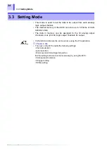
3.3 Setting Mode
28
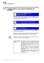
3.3.5
Setting the D/A conversion format/logic bit
position
When CAN definition data is entered by pressing the [
ENT
] key, the
D/A conversion format ([
B
]
or [
M
]) flashes for an analog channel; the
bit position flashes for a logic channel.
Hold down the [
SEL
] key until the flashing section shows the desired
value.
To enter the D/A output format or bit position, press the [
ENT
] key.
This enters the new setting.
After the D/A output format or bit position is selected by pressing the
[
ENT
] key, the channel number indication starts flashing again.
1
Enter the CAN definition data.
(Section 3.3.4, 27p.)
2
Press the [SEL] key, and set the value.
3
Press the [ENT] key.
CAN data conversion and output are stopped for all channels while the D/A
conversion format/logic bit position is being set.
D/A conversion
format
This format is used to select analog signal output
in a range from -5 to +5 V or 0 to +5 V. Selecting
Bipolar [
B
] sets the output range from -5 to +5 V;
selecting Monopolar [
M
] sets the output range
from 0 to +5 V.
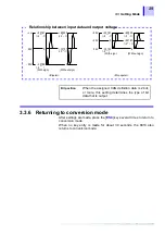
The D/A resolution is 16 bits in both cases. When
the data length is 16 bits, the relationship
between input data and output voltage is as
follows:(29p.)
(When the data length is N (bits), replace "16" in
the factorial of "2" shown in the diagram with "N"
in calculation.)
Summary of Contents for 8910
Page 1: ...8910 Instruction Manual CAN ADAPTER EN Aug 2018 Revised edition 7 8910A981 07 18 08H ...
Page 2: ......
Page 8: ...Contents vi ...
Page 18: ...Notes on Use 10 ...
Page 44: ...3 5 Operation Map 36 ...
Page 48: ...4 2 Program Setup 40 ...
Page 56: ...5 4 Operation Flowchart 48 ...
Page 78: ...6 6 Editing in Another Window 70 ...
Page 90: ...7 4 Setting the ID Filter 82 ...
Page 99: ...91 9 2 Setting Data Printout ...
Page 130: ...10 2 Using the 8910 with the 8841 8842 MEMORY HiCORDER 122 ...
Page 147: ......
Page 148: ......
Page 149: ......
Page 150: ......

