43
5.2 Starting Up the Condition Setting Program
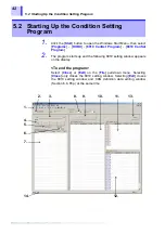
1. Toolbar
Various operations can be conducted by clicking
appropriate icons on the toolbar.
The colored icons effective in this window (from the
left) are:
• [
New
] for the 8910 setting file
• [
Open
] for the 8910 setting file
• [
New
] for the CAN definition data file
• [
Open
] for the CAN definition data file
• [
Save
] for the currently open file
• [
Save as
] for the currently open file
• [
] for setting data
Checking [
Toolbar
] on the [
View
] pull-down menu
displays the toolbar.
2. ID trigger setting
The ID trigger is a function that outputs a pulse wave
from a selected logic channel at ID message input.
This section is used to enter the ID trigger setting.
3. CAN definition data file selection
This shows the name of the CAN definition data list file
currently selected. To change the file, click the [
...
]
button on the right side.
4. CAN definition data edit button
This button is used to edit CAN definition data. It
allows the editing of existing data and creation of new
data.
5. CAN port selection
This is used to select CAN1 or CAN2 input port of the
8910 for data input.
6. CAN definition data list detail display
Checking this item displays all setting items of
definition data in list format. When this setting is off,
only the necessary items are displayed.
7. CAN definition data list
This section displays the content of the downloaded
CAN definition data file. In the initial state, the content
of the previously used file is displayed.
8. ID filter setting
Each input port can be set with a filter to prevent the
reception of messages in standard or extended format.
9. 8910 registration list edit button
This button is used for editing an 8910 registration list.
It allows the editing of an existing list and creation of a
new list.
10. 8910 registration list content
This section displays the CAN definition data to be
registered on the 8910 CAN ADAPTER. Up to 50
items of definition data can be registered on the 8910.
11. Analog output allocation list
This list displays the data to be output through analog
output channels 1 through 12 of the 8910 CAN
ADAPTER.
12. Logic output allocation list
This list displays the data to be output through logic
output channels A through F of the 8910 CAN
ADAPTER. Each line on the display represents one bit.
13. Send button
This button transmits the settings made in this window
to the 8910 CAN ADAPTER.
Summary of Contents for 8910
Page 1: ...8910 Instruction Manual CAN ADAPTER EN Aug 2018 Revised edition 7 8910A981 07 18 08H ...
Page 2: ......
Page 8: ...Contents vi ...
Page 18: ...Notes on Use 10 ...
Page 44: ...3 5 Operation Map 36 ...
Page 48: ...4 2 Program Setup 40 ...
Page 56: ...5 4 Operation Flowchart 48 ...
Page 78: ...6 6 Editing in Another Window 70 ...
Page 90: ...7 4 Setting the ID Filter 82 ...
Page 99: ...91 9 2 Setting Data Printout ...
Page 130: ...10 2 Using the 8910 with the 8841 8842 MEMORY HiCORDER 122 ...
Page 147: ......
Page 148: ......
Page 149: ......
Page 150: ......

