


38
_____________________________________________________________________________________________
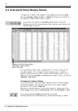
5.6 Other Display Modifications
______________________________________________________________________________________________
5.6.5 Setting the Legend Channel Format
Comment
Channel
Settings
5.6.6 Turning the Channel Marker On and Off
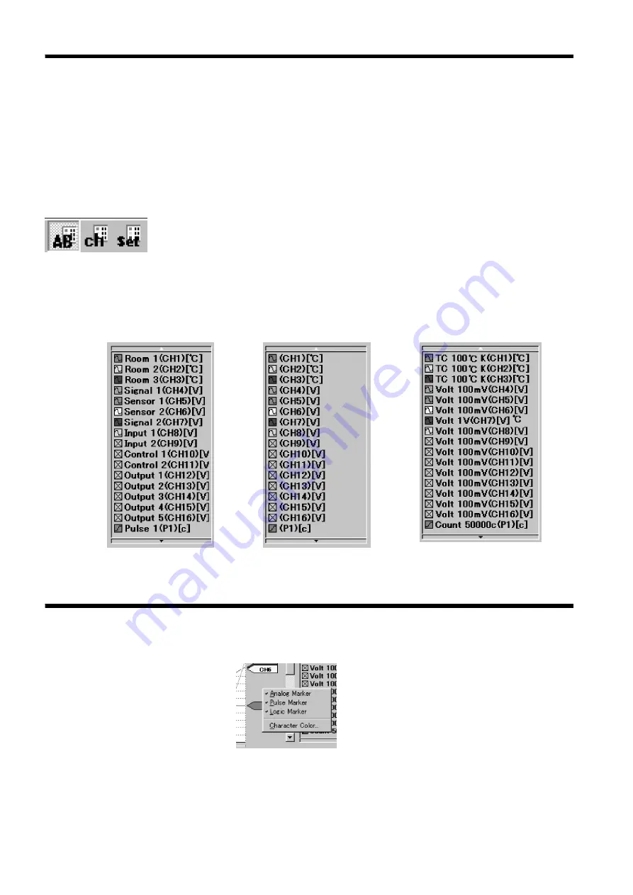
You can choose a legend channel format from the following 3 types:
1. Comment: Displays the comments set for each channel.
2. Channel: Displays the channel number.
3. Settings: Displays the input type and the range.
On the [
View
] menu, point to [
Channel Notation
], click [
Comment
],
[
Channel
], or [
Setting
], then make the settings.
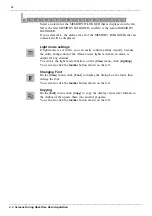
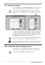
You can also click the
toolbar
buttons shown on the left.
Starting from the left: Comment, Channel, and Settings are shown.
You can also right-click anywhere inside the legend display frame, point to
[
Channel Notation
], then click [
Comment
], [
Channel
], or [
Setting
].
Similarly, to change the character color and font, right-click anywhere inside
the legend display frame, click [
Text Color
] or [
Font
], then make the
changes.
Right-click the channel marker, then click Analog, Pulse, or Logic to
activate or deactivate the display.
You can also click [
Text Color
] to change the character color of the channel
marker.