41
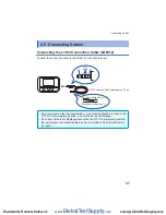
Connecting Cables
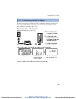
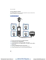
Measurement procedure
CT6590 Sensor Unit
LR8513
2
3
4
5
6
7
0.00 A
Zero adjustment
1
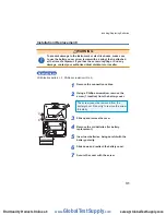
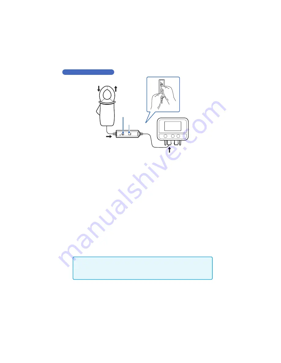
Supply power to the CT6590 Sensor Unit (battery or AC adapter).
There are two power supplies, batteries (accessory) and AC adapter (optional).
Use the AC adapter when operating the instrument continuously for a long period of time.
2
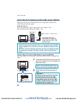
Connect the clamp sensor to the CT6590.
3
Connect the CT6590 to the LR8513.
4
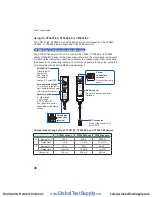
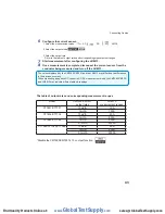
Select the range with the selector switch.
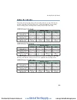
Refer to “Output rate and range of the CT9691-90, CT9692-90, and CT9693-90 Sensor”
(p.40) and select the range appropriate for the measuring instrument.
The voltage corresponding to the input current is output.
For example, 100 mV is output for 10 A when the L range is selected on the CT9691.
The voltage corresponding to the input current is output.
For example, 100 mV is output for 10 A when the L range is selected on the CT9691.
5
Turn the zero adjustment knob and perform zero adjustment so that the
measured value indicates around 0 A in the instrument screen.
Before starting measurement, turn the zero adjustment knob on the CT6590 and correct
any deviation in the output.
• The zero adjustment knob has a design that is not easy to turn so it is not turned
accidentally after zero adjustment.
• If the measured value does not indicate around 0 A after zero adjustment, send
the CT6590 and clamp sensor for repair.
6
Wire the clamp sensor to the object to be measured.
7
After the measurement, remove the clamp sensor.
www.
GlobalTestSupply
.com
Find Quality Products Online at:
sales@GlobalTestSupply.com

