1.3 Names and Functions of Parts
14
1.3 Names and Functions of Parts
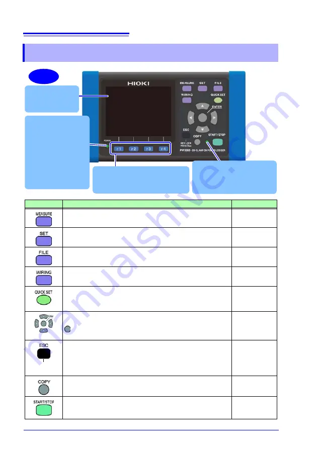
Front
Display
3.5" TFT color LCD
POWER LED
Lights up when the
POWER switch is
turned on and power is
supplied to the instru-
ment. (p. 37)
Flashes if the backlight
has been turned off
due to the AUTO OFF
setting. (p. 71)
Recording LED
Flashing green: When in the
recording standby state
Solid green: When recording
Function key (F1 to F4 key)
Select and change display contents
and settings.
Key
Description
Reference
Measurement key. Displays the Measurement screen and
switches to the next screen.
Settings key. Displays the Settings screen and switches to
the next screen.
File key. Displays the File (SD memory card/internal mem-
ory) screen and switches screens.
Wiring key. Displays the Wiring Diagram/Wiring Check
screen and switches screens.
Quick Set key. Displays the Quick Set screen and switches
to the next screen.
Measurement
guide
Cursor keys. Moves the cursor on the screen. The cursor
keys are also used to scroll graphs and waveforms.
: Enter key. Selects items on the screen and accepts
changes.
Cancel key. Cancels selections and changes, reverting set-
tings to their previous values. Switches to the previous
screen. Pressing and holding the Cancel key for 3 or more
seconds activates the key lock (which is canceled by press-
ing and holding the key again).
Screen Copy key. Outputs an image of the currently dis-
played screen to the SD memory card.
Start/Stop key. Starts and stops recording.
KEY LOCK
Press 3 sec
Summary of Contents for PW3360-20
Page 2: ......
Page 66: ...3 8 Verifying Correct Wiring Wiring Check 58 ...
Page 104: ...7 2 Settings That Can Be Added to Quick Set Settings 96 ...
Page 120: ...8 8 Formatting the SD Memory Card or Internal Memory 112 ...
Page 166: ...11 4 Outputting a Pulse Signal 158 ...
Page 210: ...13 4 Disposing of the Instrument 202 ...
Page 218: ...A8 ...
Page 222: ...Index Index 4 ...
Page 223: ......
Page 224: ......


