background image


Name of Each Part 


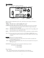
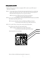
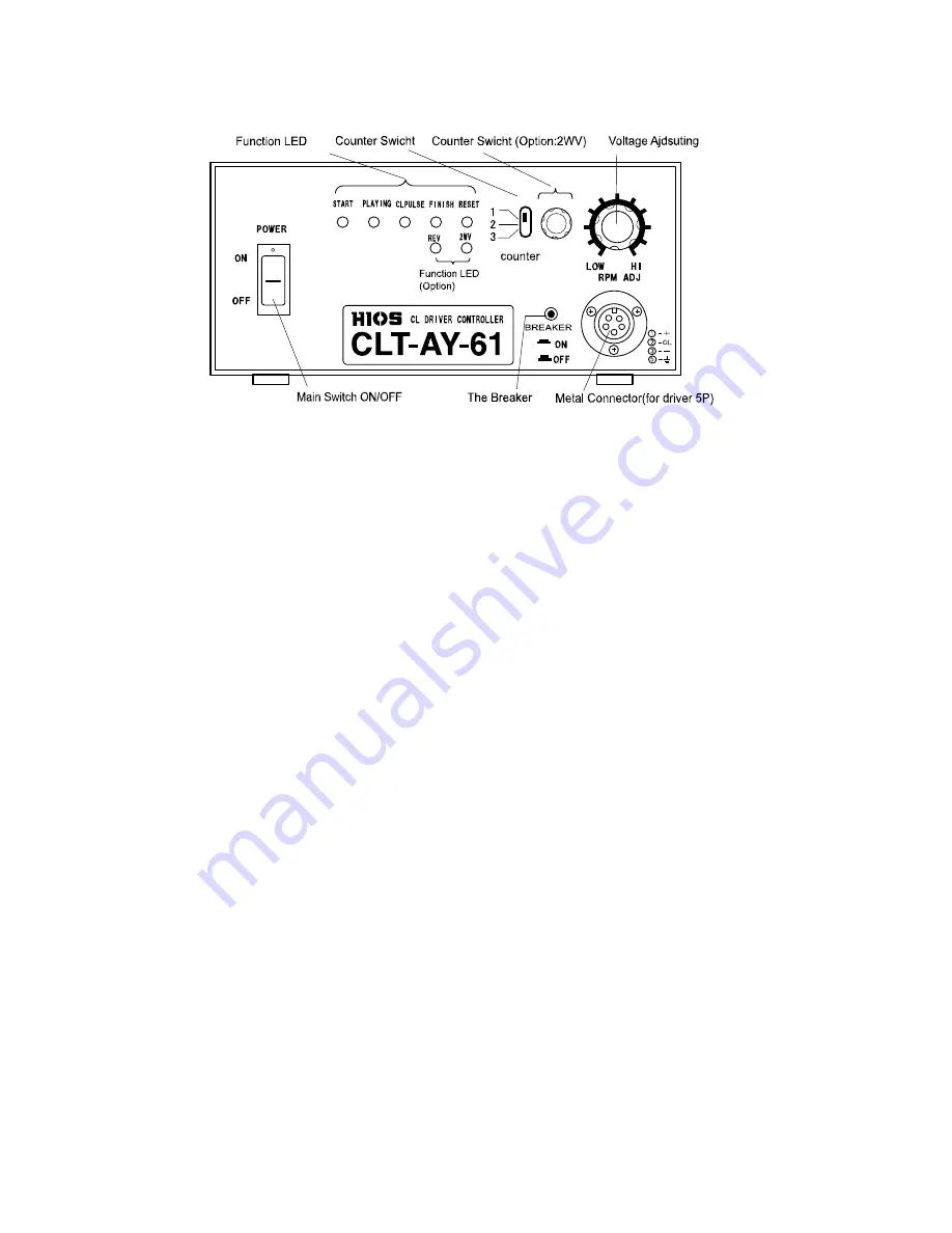
Front Panel (CLT-AY-81 is similar to CLT-AY-61) 


Main Switch: ON and OFF AC100, 120V or 220 - 240V Power with is brought to Transformer. 
Function Leeds: 
  START   : This lamp turns on while the START signal is input. 
  PLAYING : This lamp turns on while the START driver rotates. 
CL PULSE : This lamp indicates that the pulse signal output when the torque detection SW of 

driver detects the torque. The rotation of diver will also be stopped by this pulse 
signal provided to the transformer. 

FINISH   : This lamp turns on when the screw tightening is finished. And it keeps lighting until 

the next starting or reset command is executed. 

RESET    :    This lamp turns on while any trouble is occurred on tightening or overtime condition. 
 
*Note; In case that output circuit is short or load is over, CL PULSE and RESET LEDs turn on 

simultaneously and output to the motor of driver will be stopped. In such case, check 
the driver. 

 
OPTIONS (Followings are optional specifications.) 

2WV : This lamp turns on while the driver works at Low Level of rotation, described at the 

optional LOW-HI specifications. 

REV : This lamp turns on while the driver works at Reverse rotation, described at the optional 

REV specifications. 

   
COUNTER SW : Number of the impact for completion of tightening is selected 
                By this SW; 1= 1 time of impact 
                            2= 2 time of impact 
                            3= 3 time of impact 
 
Voltage Adjusting 
   Dial    : You can adjust the times of rotation steplessly in a provided range. 
    Circuit Breaker : This protects the secondary side (driver, circuit) of transformer. 
 

Summary of Contents for CLT-AY-61

Page 1: ...atic Controlled Systems For Electric Screwdrivers Operation Manual CLT AY 61 CLT AY 81 March 2017 HIOS Inc 1 16 5 Akiyama Matsudo City Chiba Pref Japan Phone 81 47 392 2001 FAX 81 47 392 7773 Operation Manual No ET A035 17A ...

Page 2: ...ble of Contents Cautions in Operation 2 Selection of Controllers 2 Name of Each Part 3 4 Setting of switches on the PCB 5 Input and Output circuit 6 Timing Chart for Pulse input starting system 7 Timing Chart for Reading starting system 8 Timing Chart of Option REV Starting System 9 Timing Chart of Option 2WV Starting System 9 Notice of using Transformer for Multiple Axes 10 Procedure of Setting a...

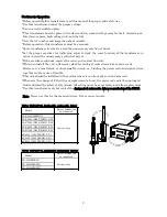
Page 3: ...ontrol terminal or power code However too much slack or unreasonable wiring ex binding the power code and signal wires together will be cause of trouble This unit should be installed in the system where it can be easily seen and removed Whenever the change of I O setting or replacement of unit the power code must be unplugged And confirmed the safety of all systems All setting must be same before ...

Page 4: ...rns on while any trouble is occurred on tightening or overtime condition Note In case that output circuit is short or load is over CL PULSE and RESET LEDs turn on simultaneously and output to the motor of driver will be stopped In such case check the driver OPTIONS Followings are optional specifications 2WV This lamp turns on while the driver works at Low Level of rotation described at the optiona...

Page 5: ...at the both end of the terminal When you do it unscrew each of screw little by little The table below is the status of switches of the PCB set at HIOS factory If you change the setting refer to the section of Input Output setting Fuse Holder 1 each of Fuse and Spare Fuse are installed If the Fuse is cut then the lamp of AC Switch and LED lamps do not lit replace with Spare Fuse ...

Page 6: ...ward Rear Panel side R Reading Starting SW102 You can use both types H type or N type of automatic driver manufactured by HIOS The delivery time setting is for H type SW102 is placed toward Rear Panel side XH H type HIOS specification toward Front Panel side XN N type Nittoh specification SW103 You ca select the way of input Open collector Input Voltage Input The delivery time setting is the open ...

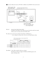
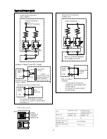
Page 7: ...6 Input and Output circuit ...

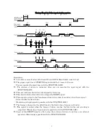
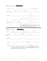
Page 8: ...hart indicates that driver was stopped by RESET signal T6 This signal is output to the Transformer from driver when from driver when the torque of driver reaches the fixed value Monitoring of input signal is possible with the FUNCTION LED T7 The timing is changed as the dotted lines by the fixed value of torque up Counter T8 This signal is output when the torque of driver reaches the fixed value a...

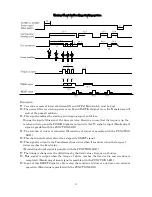
Page 9: ...ION LED T4 The rotation of driver is indicated Monitoring of signal is possible with the FUNCTION LED T5 This chart indicates that driver was stopped by RESET signal T6 This signal is output to the Transformer from driver when from driver when the torque of driver reaches the fixed value Monitoring of input signal is possible with the FUNCTION LED T7 The timing is changed as the dotted lines by th...

Page 10: ...9 Timing Chart of Option REV Starting System Timing Chart of Option 2WV Starting System ...

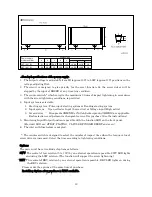
Page 11: ... are connected the capacity of current should not exceed the range of possibility to be driver by sequencer or controller Procedure of Setting and Installation When the installation or setting this Transformer read this manual well be make sure the safety operation CAUSION Whenever installing or setting the Transformer must be unplugged 1 Confirm the matching or driver 2 Select all built in switch...

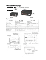
Page 12: ...11 CLT AY 61 CLT AY 81 Power supply for Automatic screwdriver CLT AY 61 2WV option 2WV REV or 2WV REV Option CLT AY 81 Specifications ...

Page 13: ...ive 3 Screw driver Hios product HH XH or Nittoh Seikou product HH XN are applicable Each selection or adjustment is changeable even after purchase See the instructions 5 Monitoring Input Output function is possible with the function LED on the front panel Provided LED are STRAT PLAYING CL PULSE FINGISH RESET and so on 6 The inlet with fuse holder is adopted The counter switch is designed to select...

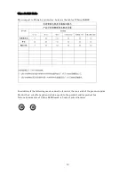
Page 14: ...elow is the table of China RoHS2 In addition if the following mark cannot be found at the rear side of the product and or Product box cut off a mark and stick a mark to the product and or product box Note minimum size of China RoHS mark is 5mm at outer diameter ...

Reviews: