■
I/O
34
/
52
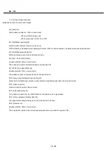
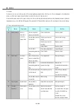
11.3 I/O input signal sequence
■ Sequence of each input control signal
IN0 (Start IN)
Start enable conditions: - When in auto mode
- When CH No has been set
- When alarm reset IN (IN 12) is OFF
IN1 (FOR/REV switching IN)
Switch enable condition: When in auto mode
FOR (clockwise): Enables screw tightening direction, REV (counterclockwise): Enables screw loosening direction
IN2 (Auto/Manual switching IN)
Switches between auto mode and manual mode
IN3 (CH1 IN) to IN6 (CH8 IN)
Enable condition: When in auto mode
The channel number is selected based on the specified bit.
IN7 (PTN1 IN) to IN9 (PTN4 IN)
Enable condition: When in auto mode
The pattern number is selected based on the specified bit.
IN10 (Temporary/Full tightening switching IN)
Switches to full tightening operation, when temporary tightening operation is being performed.
IN12 (Alarm reset IN)
Alarm is reset if an alarm has occurred.
IN13 (Emergency stop IN)
If the shaft is in operation, the shaft rotation stops and an error is generated.
IN14 (Torque judgment display clear IN)
The judgment message displayed on the touch panel is cleared.
IN15 (Reverse IN)
Enable condition: When in auto mode
The screwdriver rotates in the screw loosening direction only while the signal is ON.
Summary of Contents for DCD-40L
Page 1: ...Current Controlled Screwdriver DCD 40L 115W Instruction Manual ET A070 19A HIOS Inc ...
Page 27: ... Operation timing charts 27 52 Pattern 2 ...
Page 28: ... Operation timing charts 28 52 Pattern 3 ...
Page 29: ... Operation timing charts 29 52 Pattern 4 ...
Page 37: ... I O 37 52 Timing chart for normal operations when torque judgment is NG ...
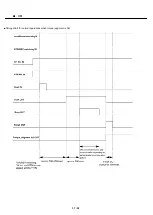
Page 38: ... I O 38 52 Timing chart when emergency stop signal is input ...


