background image

- 4 - 


(9) 

No Error Time 
for double fastening 


No error time can be set with three bars + values in order to avoid unnecessary 
errors during double fastening. 


This setting is enable only when fastening is done properly.   

Display range: 0.0

9.9


Setting range: 0.0

9.9 sec   


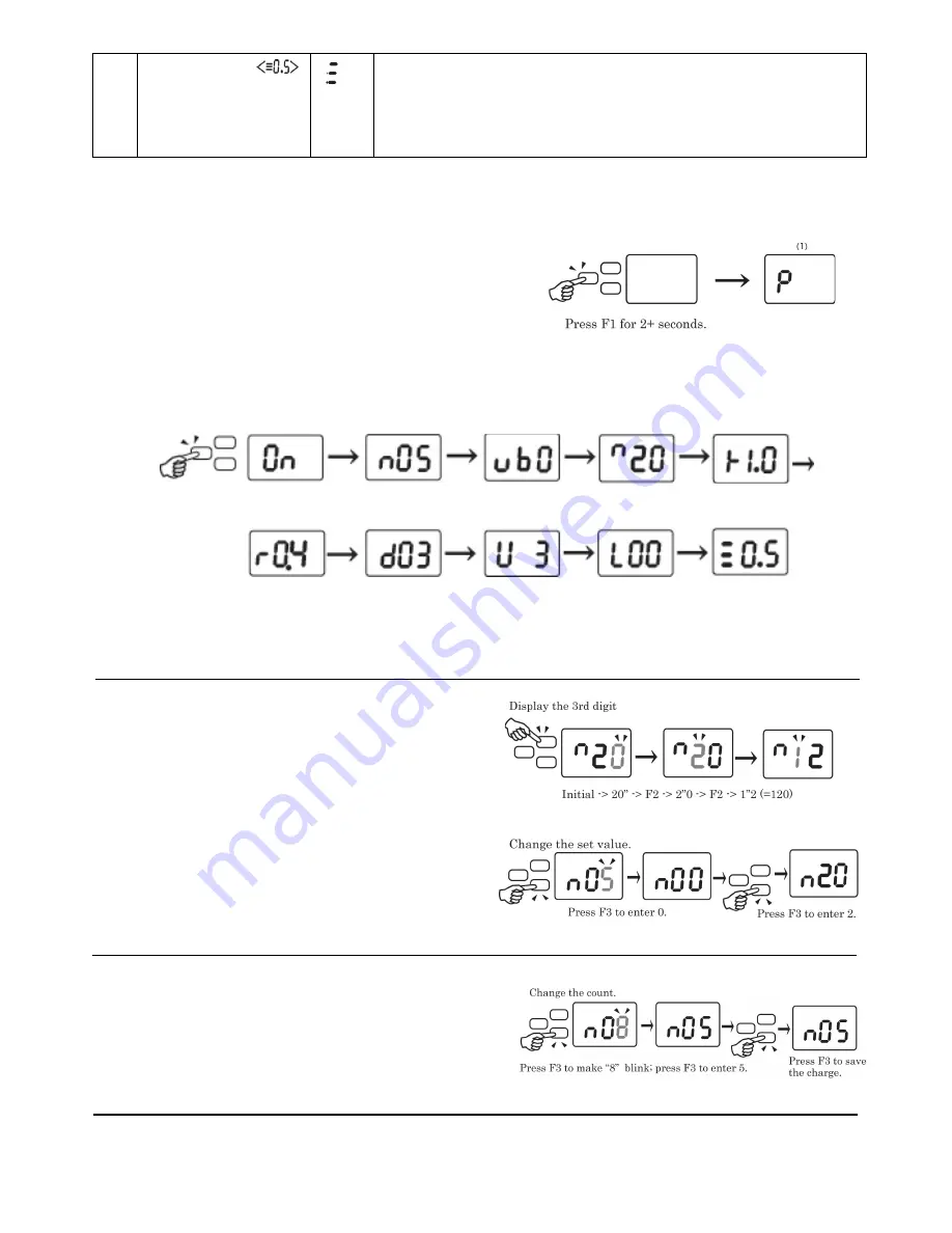
 Screw Counter   

1.


Changing to the Setup Mode: 

Press  and hold the  F1  Button  until  “P”  then the 
“On” is displayed.   
 

2.


Setting Mode: 

Pressing the F1 button allows you to scroll through each setup functions. 
Refer to “List of setup functions” on page 3 for the changing and setting any functions. 


Note: The no. of motor revolutions is displayed up to triple digits. 


3. Value Setting for Each setup functions: 


Verify the hundreds (3

rd

) digit. 

Press the F2 Button to change the figure position 
for setting.   


Change the value.   

Pressing the F3 button increases the value one by one. 


Press and hold the F1 button until the buzzer sounds 
twice to save the change. 


4. Change cycle count. 
  Press F1 Button for more than 2 sec. to increment to 
  display number. Follow the procedure described in   

3 above. 
The count can be set between 1 and 99. 


(Count )   


Pulse/ Min 


Pulse/ Max 


  (Work Reset Timer) 


(Reverse Count Timer)     


(System)    


  (Over Time/


  (Total No. of the


     (No Error Time for   


   Short Time) 

driver shut off)       double fastening) 

     (1)                     (2)                  (3)


(3)


4


     (5)                     (6)                  (7)


(8)


9


(Count) 

(Min. revolutions) 

(Max. revolutions) 

(Work Reset Timer) 

Summary of Contents for JUKUREN BLG-BC2 series

Page 1: ...anual August 2018 Note BLG BC2 I O Cable set is optional P N BLG BC2 3010 Contents BLG BC2 I O Cable Application software Including the instruction manual Communication specifications HIOS Inc 1 16 5 Akiyama Matsudo City Chiba Pref Japan 270 2223 TEL 81 47 392 2001 FAX 81 47 392 7778 NO ET A011 BC2 18A ...

Page 2: ... count is displayed The count decreases with each screw fastening operation and the remaining screw fastening count is displayed 2 Function display section The symbol corresponding to the function is displayed in the setup mode See page 3 3 F1 Button Press and hold the F1 button until the P then the On is displayed Continue to press the F1 button to scroll through the setup functions Press and hol...

Page 3: ...ton Press to confirm the reference values of Pass Fail including the acceptable range Example Assuming the reference values including the acceptable range are from 90 to 120 the Pass range is from 91 to 119 Note In order to complete Direct Teaching make sure to work through all the steps 1 4 5 F2 Button Press and hold until the buzzer sounds twice to complete Direct Teaching 6 All set List of setu...

Page 4: ...it based on the Reverse Count Timer set value 5 Reverse Count Timer The time period until the Reverse Count is performed is set Set the Work Reset Timer operation time based on the time period up to when the Reverse Count is performed Setting range 0 1 1 0 second Note It is available when the Reverse Count Enable has been set in the System setting 6 System Setting Each buzzers and Reverse Count En...

Page 5: ...The no of motor revolutions is displayed up to triple digits 3 Value Setting for Each setup functions Verify the hundreds 3rd digit Press the F2 Button to change the figure position for setting Change the value Pressing the F3 button increases the value one by one Press and hold the F1 button until the buzzer sounds twice to save the change 4 Change cycle count Press F1 Button for more than 2 sec ...

Page 6: ...ity The count is to be returned to the default value during the screw fastening operation Pressing the F3 button for 2 seconds or more resets the screw fastening count value If you fasten a screw after the driver turns counterclockwise There may be some difference in results of motor revolutions after the driver turns counterclockwise as the start position may have changed In this case the start p...

Reviews: