3. Assembly and installation procedure HIRO 160 Q
17
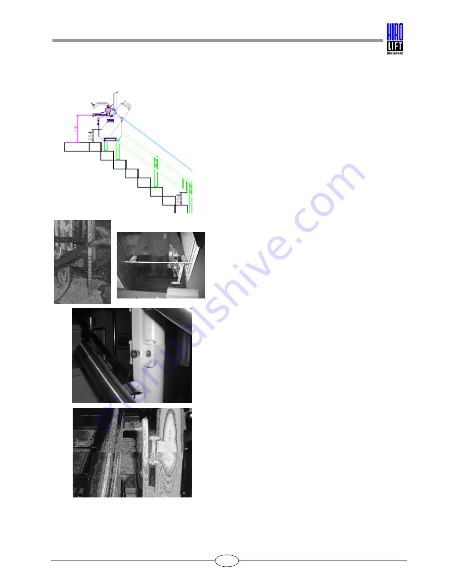
The dimensions for further aligning the guide rail
beams are given in the lift unit drawing.
At each join position between the guide rail beams,
the drawing gives the height dimension from the
stair tread to the centre of the lower guide rail tube.
The guide rail braces must be aligned
perpendicularly. The guide rails can be adjusted at
the fixings by altering the position of the clip.
Check all the dimensions specified in the drawing.
After adjusting the position of the guide rails, check
that all fixings and supports are tightened
sufficiently, and re-tighten all bolts and screws if
necessary.
Check the dimensions of the guide rail track for
accuracy (centre distance).
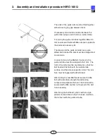
The centre distance, measured vertically from the
centre of the upper guide rail tube to the centre of
the lower guide rail tube, must be 250 mm.


