27
21
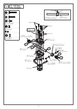
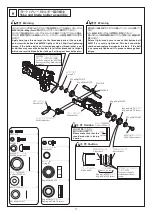
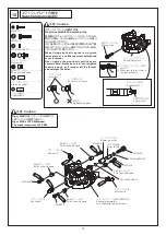
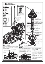
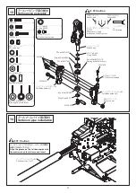
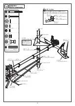
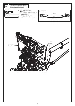
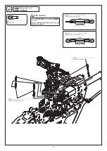
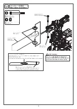
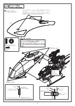
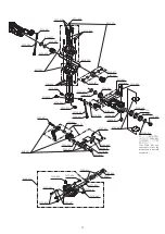
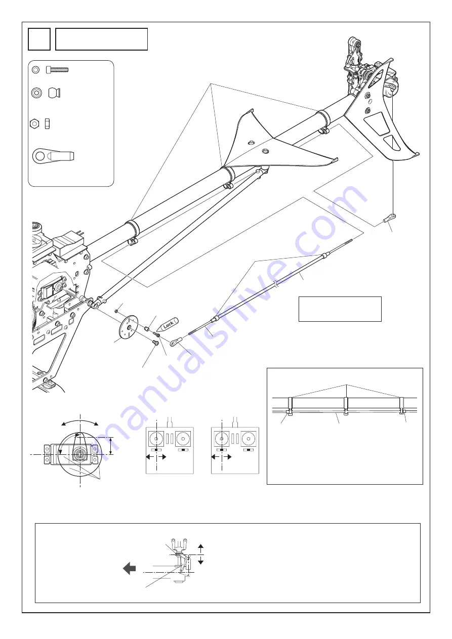
ラダーのリンケージ
Rudder linkage
M2
ロッドエンド
........................ 2
M2 rod end
M2X8CS ................................... 1
EX ø5
ボール台付
..................... 1
EX ø5 ball with stand
M2
ナット
.................................. 1
M2 nut
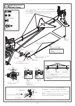
テールブームパイプに対して
3°
〜
5°
の位置(初期設定)
Positioned at 3° to 5° to the tail boom pipe (initial setting)
ホバリングの回転数によって変化しますので、フライトをして調整
します。
Because it changes depending on the number of rotations when
hovering, first fly the unit and then make adjustments.
M2
ロッドエンド
M2 rod end
M2
ロッドエンド
M2 rod end
M2X8CS
EX ø5
ボール台付
EX ø5 ball with stand
M2
ナット
M2 nut
サーボホーン
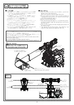
Servo horn
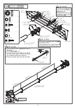
ラダーコントロールロッド
L=642
Rudder control rod L=64
POM
パイプ
2.5X3.5X480
POM pipe 2.5X3.5X480
POM
パイプは
480mm
にカット
して使用。
Cut POM pipe to 480 mm.
POM
パイプ
POM pipe
サーボに付属のネジ
Screw included with the servo
リンケージロッドがスムーズに動くようにラダーガイドの位置を調整して
からネジを締めてください。
Before tightening the screws, please make sure that the rudder guides
are neatly aligned so that the linkage rod can move smoothly.
ラダーガイドの両側に
5mm
ほどの長さにカットしたシリコン
チューブをはめて固定します。
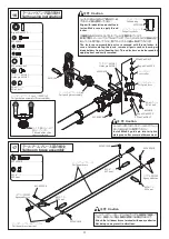
In order to secure the POM pipe in its appropriate position,
attach approximately 5mm long silicon tubes on both sides
of rudder guides.
3
゜
〜
5
゜
90
°
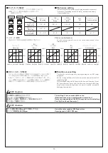
左
Left
左
Left
左
Left
左
Left
カット
Cut
15mm
右
Right
右
Right
右
Right
右
Right
中立
Neutral
中立
Neutral
モード
I
Mode I
モード
II
Mode II
中立
Neutral
中立
Neutral
テールピッチプレート
Tail pitch plate
機首方向
Direction of the nose of the unit
テールピッチレバー
Tail pitch lever
上から見た図
Top view illustration
送信機
スティック、トリム
:
ニュートラル
Transmitter
stick/trim: neutral
サーボホーン
:
ニュートラル
Servo horn: neutral
シリコンチューブ
Silicon tube
シリコンチューブ
Silicon tube
ラダーガイド
Rudder guide
シリコンチューブ
Silicon tube


