background image

MADE IN JAPAN


C

 2003

No.104471

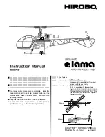
主要諸元
ギヤ比
無線機

適合エンジン


 / 9.625 : 1 : 5.5
 / 

ヘリ用プロポセット

 (

別売

)

   Programmable transmitter set for model 
   helicopters (Sold separately)
 / 30

〜46クラス

 (

別売

)  

   30-46 class engine (Sold separately)

※46クラスエンジンの搭載には別途購入品が必要です。
 (ご注意:50クラスエンジンの搭載はできません)
※Additional parts must be purchased in order to mount 
 46 class engines. (Note that the 50 class engines 
 can not be mounted.)

Main features
Gear ratio
Radio control device

Compatible engine

組立前に必ずこの説明書を最後まで、よくお読みにな
り、正しくお使い下さい。特に、「安全のために必ず
お守り下さい」は、飛行前に必ず読んで下さい。
この説明書は、大切にお手元に保管して下さい。
製品改良のため、予告なく仕様を変更する場合があります。

Before assembly, make sure to completely read this 
instruction manual. In particular, make sure to read the 
"Follow these rules to ensure safety" section before 
operating the unit. 
Keep this instruction manual in a handy, safe place.
In order to make improvements to this product, 
specifications may be altered without prior notice.

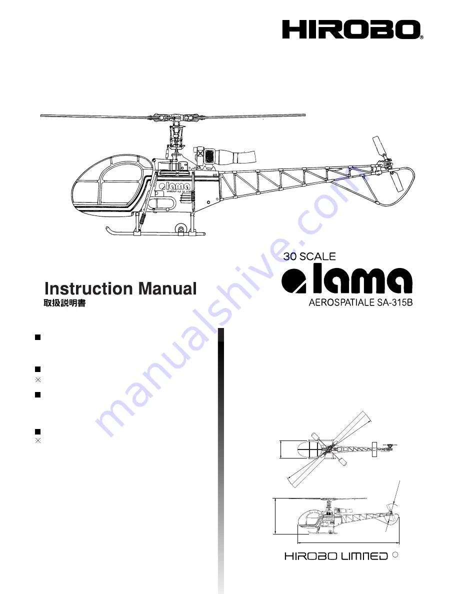
1190mm

404mm

262mm

1244mm

225mm

Summary of Contents for Lama SA-315B

Page 1: ...engines can not be mounted Main features Gear ratio Radio control device Compatible engine Before assembly make sure to completely read this instruction manual In particular make sure to read the Foll...

Page 2: ...to failure to follow these instructions may result in severe injury or death Mishandling due to failure to follow these instructions may result in serious harm Do not attempt under any circumstances...

Page 3: ...he engine check that any tools used in the assembly installation or maintenance of the unit have been put away 7 Inspect each part Before starting the engine check for any damaged parts and make sure...

Page 4: ...in an awkward posture Do not operate seated or lying down Because slopes are slippery exercise caution so as to not loose your footing 2 Stop the engine in the following situations When adjusting the...

Page 5: ...ion of Hirobo s Sales Department Individuals lacking proper knowledge or tools necessary for repairs may not only impair the performance of the unit but may also increase the risk of accidents or inju...

Page 6: ...tion of any part replace it immediately using only genuine parts 1 Beginners should have safety and technical guidance from an experienced individual Teaching yourself is extremely dangerous 2 Check t...

Page 7: ...and check that there are no other people or dangerous obstacles 6 Just before take off adjust the tracking each rotor s track Even when checking the tracking do not get nearer than 5 meters from the...

Page 8: ...parts cannot be exchanged or returned In the event of any missing or defective parts have the store from where you purchased the product stamp your user s card and send it with the name and descripti...

Page 9: ...5 M2X4 5 shoulder screw 1 Tapping screw 1 M3X10TS 1 2 Tapping screw 2 M3X8TS 2 Countersunk screw M3X12 M3X12 countersunk screw Countersunk tapping screw M3X10 TS 1 M3X10 countersunk TS 1 Flat washer...

Page 10: ...lane 15 20 15 Nitromethan approx 20 oil 2515 200 4 000 23 20 23 Nitromethan approx 20 oil 2515 201 5 000 30 20 30 Nitromethan approx 20 oil 2515 202 6 000 30 F3C 10 30 Nitromethan F3C Contest approx 1...

Page 11: ...y 1 200 Can be used inside the glow engine and on silicon components Not fit for drinking 2515 121 R C Dust Blower Spray 1 800 A strong jet of air that blows away dust in a single shot 2515 122 R C Co...

Page 12: ...levator lever LM LM elevator shaft Brg 5X8X2 5 4E 4 E ring 5 5 ball 3X4 5X0 5FW M2X10CS Brg 3X6X2 5F Brg 3X6X2 5F M2X8PH LM LM elevator rod Apply grease Starter shaft 4X6X0 5FW Clutch bell Brg 8X16X5Z...

Page 13: ...uel tank cap M5 M5 nut Fuel tank sinker FW 5X10X1 FW 5X12X0 8 Brg 8X19X6ZZ M3 M3 nut M3 M3 nut Brg 8X19X6ZZ Brg 5X11X5ZZ M3X20PH M3X20PH M2 6X6CS Metal bevel pinion gear Clutch bell M3X25PH Fuel tank...

Page 14: ...3X3SS Align the M3X3SS with the gap M3X3SS Mounting M3X3SS 0 3mm Starter shaft Joint shaft cover Counter joint shaft Gap Joint shaft cover Counter joint shaft Lock Lock M3X3SS 2 M3X18PH 2 M3X8PH 2 M2X...

Page 15: ...14 Servo frame assembly 6 M3X12 TS 16 M3x12countersunk TS M3X12 TS M3X12 countersunk TS M3X12 TS M3X12 countersunk TS M3X12 TS M3X12 countersunk TS M3X12 TS M3X12 countersunk TS...

Page 16: ...X12PH M3X6 countersunk screw Cooling fan Clutch shoe Engine mount M3X12CS M2 M2 nut Needle extension lever M3 M3 set screw included with engine 5 5 ball Lever DA DA ball stand Drive nut included with...

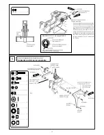
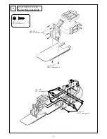
Page 17: ...TS M3X14CS M3X28CS Muffler spacer M3X28CS 2 M3X14CS 4 M3X12 TS 8 M3X12 countersunk TS FW 3X9X1 4 1mm Set the engine approximately 1mm lower than the fully raised position Adjust so that the clutch be...

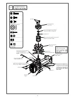
Page 18: ...allation M3X16CS 1 M3 1 M3 nylon nut M3X3SS 2 Main mast Mast lock M3X16CS M3 M3 nylon nut M3X3SS M3X3SS Caution M3X3SS Completely raise the main mast insert the mast lock and fasten with an M3X3SS scr...

Page 19: ...m Control arm 5 5 ball 2X11 8 2X11 8 needle pin M3X10PH Brg 3X6X2 5F Brg 3X6X2 5F 3X4 5X0 5FW 3X4 5X0 5FW M2X8PH Upper Lower 12 Blade holder assembly M2X10CS 2 5 2 5 ball M3X8TS 2 4 M3X8TS truss 2 Brg...

Page 20: ...sert it completely into the yoke Yoke Center hub Damper rubber M4 M4 nylon nut M3X8CS C 5X8X5 5 FW 4X9X0 8 Lock Lock Seesaw assembly 14 M3X12PH 2 M3X6PH 2 M2X8PH 4 5 4 5 ball Brg 3X7X3 2 Brg 3X6X2 5F...

Page 21: ...l M3 M3 nut Cover film Stabilizer bar Stabilizer stopper M4X4SS B A A B 132mm Swashplate assembly 16 E Pivot bolt E E Pivot bolt E D Pivot bolt D D Pivot bolt D Lower swash plate Upper swash plate Loc...

Page 22: ...nylon nut M3X14 TS 1 M3X14 countersunk TS Make sure to install the radius arm to the longer pivot of the swash upper plate Caution M3X18CS Center hub M3 M3 nylon nut Radius block Radius arm Swash plat...

Page 23: ...movement is smooth Caution Align with the tail shaft s indentation and fasten Make sure to apply thread locking agent Caution M2X4 5 Note the insertion direction of the M2X4 5 rod end pin Do not over...

Page 24: ...Tail drive pipe 1 R L M2X15PH M2 8 M2 2 R L M2X10TS 16 3 1 Combine the tail boom truss lower part and boom trusses R and L Then tighten them with eight M2X15PH and M2 nuts In order to fix the screws u...

Page 25: ...X0 5FW M3X3SS M3X12TS 2 M3X12TS 2 M3X12TS 2 M3X8PH M2 6X12TS 2 M M2 6X12TS 2 M M3X12PH M3X12TS 2 Tail truss M3 M3 nut Tail holder 21 Tail unit installation Assy Tail gear assembly M4X4SS 2X612 2X612 d...

Page 26: ...In the case of contact with the 2 joint file the truss assembly Lock Lock Lock Fully tighten 2 drive shaft insert fully Bevel pinion gear Caution M4X4SS Apply thread locking agent to the M4X4SS and fi...

Page 27: ...and fastening with a band Double sided adhesive tape Gyro sensor Caution The gyro sensor must be installed with the correct direction Install it according to the gyro s instruction manual Caution Make...

Page 28: ...g on their respective makers as well as the way they are assembled Install the wiring according to each instruction manual I II Modes I and II differ in the positioning of the throttle pitch and the e...

Page 29: ...m Approx 3mm 40mm 29mm Approx 29mm 2 Mixing arm rod 2 sets 2 Stabilizer control rod 2 sets 2 Pitch rod 2 sets After installing the main blade measure the pitch and readjust the pitch rod Caution Doubl...

Page 30: ...rim are in neutral With the transmitter s stick and trim in neutral view the unit from the front and adjust the length of the aileron rod so that the swash plate is horizontal Futaba JR SANWA Large La...

Page 31: ...view the unit from the side and adjust the length of the elevator rod so that the swash plate is horizontal 83mm 76 5mm Approx 76 5mm Elevator rod 1 8 Make holes with the 1 8 pin vise Insert the rod...

Page 32: ...gth of the collective pitch rod so that the collective pitch lever is horizontal 77mm 70 5mm Approx 70 5mm Horizontal 1 8 Make holes with the 1 8 pin vise Insert the rod from the top of the servo horn...

Page 33: ...Carburetor Throttle lever M5 M5 nut Fully open position Fully closed position I Servo horn position Throttle lever position With the transmitter s stick at full high adjust the length of the rods with...

Page 34: ...the 1 8 pin vise Insert the rod from the bottom of the servo horn 11mm Approx 11mm M3X3SS Cut out any unnecessary parts 90 90 Check that the stick and trim of the transmitter s elevator and throttle...

Page 35: ...n of the servos is reversed Switch the rotational orientation with the transmitter s reverse function Refer to the instruction manual for each transmitter Nylon nuts are used in order to prevent loose...

Page 36: ...is at full high Does the pin fall out of the slide block when the throttle stick is at full slow In case of a malfunction move the radius block vertically and adjust Check Check Caution Touches Comes...

Page 37: ...when a programmable transmitter is used Varies depending on the engine fuel muffler etc General guidelines This setting is for a common pitch curve Obtained when using a programmable transmitter May v...

Page 38: ...ide cover L M3X8PH M3X8PH M3X12TS 2 M3X8TS Oil tank Black White Joint pipe Fuel filter Sold separately 2513 038 300 To the muffler nipple To the carburetor nipple M3X8PH 2 M3X12TS 2 4 M3X8TS 2 The use...

Page 39: ...ake White Gun metallic 2 After positioning open a hole of about 2 in the bottom of the dummy engine Dark gray Level line Front M2X12PH 4 M3X8TS 6 M3X8PH 2 M3 2 M3 nut M2X10TS 2 9 M3X30TS 1 1 M3X10TS 1...

Page 40: ...ark gray Dark gray Instant adhesive Align it with the meter panel and cut so that there are no protruding parts Affix a piece of white paper to the back Use urethane paint and paint each part separate...

Page 41: ...8TS M3X6TS Align the center mark here Double sided adhesive tape M2 6X6 TS M2 6X6 truss TS M2 6X6 TS M2 6X6 truss TS Red White M2 6X12TS 2 M2 6X6 TS 10 M2 6X6 truss TS M3X6TS 2 M3X8TS 1 M3X6CS 2 P4 O...

Page 42: ...canopy are arranged as shown in the diagram Align the center marks of decals 10 and 11 Pay attention to the vertical level of decal 14 Before affixing check with the center mark of the line decal blac...

Page 43: ...ck the servo rotation direction and connection of each rod Check that the gyro case is not touching the body or canopy Check the skids are firmly mounted in the correct positions Check that the screws...

Page 44: ...orting the unit to an airfield secure it in a way so as to prevent it from falling over Failure to do so may result in the breakage of components which may compromise flight performance and safety Che...

Page 45: ...ly 1 Place the unit in the center of the room Make sure the power is turned off 2 Practice the operation of the stick while saying out loud aileron left right rudder left right elevator up down thrott...

Page 46: ...ution Check the movement OFF Reverse the above order to turn off To engine To fuel pump To fuel tank Perform a range test following the transmitter s instruction manual Separate the silicon tube at it...

Page 47: ...ollowed by the receiver 2 Connect one end of the booster cord to a 1 5V battery and the other end to the plug 3 Connect the starter to its battery 12V and check its rotational direction Completely ins...

Page 48: ...same path it does not need adjustment However if one blade is higher or lower than the other immediate adjustment of the tracking is necessary 3 The tracking is adjusted by turning the rod end of the...

Page 49: ...the unit back down I Mode II Continue to practice raising and lowering the unit from the ground until you feel comfortable with the operation of the throttle Throttle operation practice Completely ext...

Page 50: ...P 1 3 Practice circular movement Step 5 Change the unit s direction and practice hovering STEP 1 4 STEP 1 4 STEP 1 4 STEP 5 1 STEP 5 2 The more you feel accustomed to the maneuvers the smaller you can...

Page 51: ...owards a left b Move the trim towards b right Symptom c Turns towards c d Turns towards d Trim adjustment c Move the trim towards c up d Move the trim towards d down Symptom e Turns towards e f Turns...

Page 52: ...for the day follow these steps when cleaning your model 2 Never use water to wash any oil stains etc from the unit It may result in the radio controlled device malfunctioning or the rusting of metal p...

Page 53: ...f there s any damage to the silicon tubing or if there s any pressure in them that would hinder the smooth flow of fuel 8 Is the fuel filter clean 9 Is there too much fuel flowing into the engine Remo...

Page 54: ...lance replace the tail rotor blade Check the center hub YES NO YES YES YES YES YES YES NO NO NO NO NO NO Check Parts are scratched or broken Check There is vibration Set the tracking Check The main ro...

Page 55: ...move the rotor head assembly M3X18CS 4 Assy M3X16CS 4 Remove the main gear assembly M3X16CS 5 5 Pull out the main mast leaving the swash plate and wash out Use a file to remove any scratches 1 M4X4SS...

Page 56: ...II 2 Remove the blade holders and spindle in accordance with III 3 M3X6PH 3 Loosen the M3X6PH and remove the seesaw 4 M3X8CS 4 Loosen the yoke M3X8CS and remove the yoke 1 1 Remove the muffler 2 M3X14...

Page 57: ...0 500 2 310 1 575 1 470 1 365 1 470 2 310 2 415 1 680 1 575 1 470 1 575 2 415 2 625 1 890 1 780 1 680 1 785 2 625 1 2 1 3 1 3 No T E L F A X 2 5 138 726 0004 TEL 0847 40 0088 FAX 45 7670 http model hi...

Page 58: ...505 006 2525 009 2521 103 2532 047 2505 007 0402 502 Optional Optional 0402 272 2500 082 0402 545 0402 641 2533 005 2525 009 0402 507 2533 014 2506 019 0402 208 2505 002 0402 503 2500 068 0402 006 253...

Page 59: ...ed 0402 640 BE2 L 550 BE2 main blade L 550 2 2 800 4 Pre assembled root end with 4 holes 0402 641 SF2 SF2 blade holder 2 1 200 4 Main blade with 4 holes 0404 023 Radius arm 2 300 2500 057 Brg 3X 6X2 5...

Page 60: ...121 30 0402 324 0402 642 2500 081 0400 004 0402 310 0402 326 0402 327 2500 048 0402 591 2533 012 2508 003 0402 016 2500 061 0402 207 2508 003 2531 003 0412 205 0402 302 0402 321 0402 324 0402 016 2500...

Page 61: ...SE main gear assembly 1 1 set 7 800 0402 591 SE 77T SE main gear 77T 1 3 800 0402 642 SE2 SE2 clutch shoe 1 3 200 0403 211 46 OS46 FX H Muffler for 46 engine for OS46 FX H 1 2 000 0403 232 46 OS46 SF...

Page 62: ...012 2506 010 2533 016 2533 005 0402 307 2524 001 0402 512 0402 025 0402 025 0402 512 0402 322 2522 011 2524 014 0402 606 2505 007 2506 007 2532 010 2500 068 0402 801 0402 006 2532 003 2506 004 0402 61...

Page 63: ...arm set 3 1 000 2500 054 Brg 6 X 10 X 3 ZZ 2 1 200 2500 056 Brg 5 X 8 X 2 5 ZZ 2 1 200 2500 057 Brg 3 X 6 X 2 5F ZZ 2 1 200 2500 068 Brg 5 X 13 X 4 ZZ 2 1 200 2505 001 M2 M2 nut 20 200 2505 006 M3 M3...

Page 64: ...White 0402 313 0402 217 0402 216 0402 312 2526 003 2500 003 0402 314 2500 003 0402 205 2524 004 2524 003 0402 528 0402 529 0402 351 Red 0402 337 White 0402 331 0402 346 Red 0402 354 Red 0402 376 White...

Page 65: ...embly red 1 1 set 2 200 0402 347 LM Assy LM tail boom truss red 1 1 set 3 000 0402 351 LM LM horizontal stabilizer red 1 800 0402 354 LM LM landing gear brace set red 1 1 set 1 200 0402 371 LM Assy LM...

Page 66: ...y make sure to completely read this instruction manual In particular make sure to read the Follow these rules to ensure safety section before operating the unit Keep this instruction manual in a handy...

Page 67: ...402 348 LM LM side cover set red 1 1 set 800 0402 349 LM LM rear frame set red 1 1 set 800 0402 350 LM LM cabin set red 1 1 set 7 500 0402 352 LM LM decal yellow line 1 1 800 0402 353 LM LM canopy 1 2...

Page 68: ...0 100 0 NORM 20 0 45 0 65 0 80 0 90 0 IDL1 10 0 25 0 50 0 72 5 85 0 HOLD 25 0 42 0 60 0 80 0 100 0 REVO MIX INH ACT ACT 0 20 AIL ELE RUD OFST 1 0 0 0 OFST 2 0 20 0 OFST 3 0 7 0 NORM NOR 100 IDL1 NOR...

Page 69: ...65 85 100 N OFF 17 LIN 65 LIN 90 1 OFF 0 LIN 50 LIN 90 H OFF 0 LIN 55 LIN 100 ACT 0 90 ACT 1 60 ACT NORM 0 POS STNT 1 0 HOLD 0 G460T is applied to the gyro A D T Adjust the ADT to match actual flight...

Page 70: ...0 30 55 80 100 1 80 65 65 INH 100 3 HOLD 13 INH 13 INH 13 N 10 INH 67 INH 100 1 10 INH 40 INH 75 3 HOLD 20 INH 60 INH 100 PL PM PH N 30 0 0 0 0 30 1 7 2 5 3 HOLD 0 0 0 0 T CUT 100 DTM ACT BASIC OFF O...

Page 71: ......

Page 72: ...ver be any oversights mistakes or omissions that come to your attention please inform us Item not withstanding we cannot be responsible for events related to the operation of your model Note 15 2 15 3...

Reviews: