background image

47


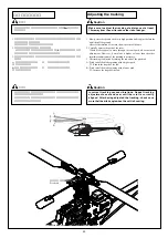
電源を入れる順番

注 意

モード


スロットルスティックは
最スローの位置


トリム

:

中立

Trim: neutral

送信機の電源スイッチを

ON!

Turn on the transmitter

受信機 の電源スイッチを

ON

Turn on the receiver

OFF

は、逆の順序

Reverse the above order to turn off

①スロットルスティックを最スローの位置にします。

Place the throttle stick in the lowest position.

受信機の電源スイッチが

OFF

になっていることを確認し、スピード

コントローラーにバッテリーを接続します。

Check that the power switch is turned off, and then connect the battery to

the speed controller.

各舵は、スティック通りに動いていますか。
プロポの説明書に従って距離テストを行ないます。

Are the rudders moving in accordance with the controls?

Perform a range test following the transmitterÕs instruction manual.

メインローターが回転しないよう、モーターの
コネクターを

2

本以上抜いてください。

To prevent the main rotor from rotating, remove two

or more motor connectors.

動作確認を行います。


送信機の電源スイッチを

ON!

Turn on the transmitter

受信機 の電源スイッチを

ON

Turn on the receiver

OFF

は、逆の順序

Reverse the above order to turn off

注意

レプトン用純正バッテリー(LEXリポバッテリー14.8V  3200mAh)は1セルあ

たりの電圧が2.7V以下になると再使用(充電)できません。 

使用後は必ずバッテリーとスピードコントローラーのコネクターを外してくださ
い。接続した状態での保管は、バッテリーが過放電し使用不能となります。 

フライト中パワーダウンを感じたらすぐに使用を中止し充電をおこなって

ください。

    ! "!#$ !  %&'( )*++,

   ",      

*- (  

.          


/     0  

1             


Summary of Contents for Lepton EX

Page 1: ...01 1 2 1 1 PCM 3 4 5 16 7 2 0 2 8 9 4 5 0 1 1 1 4 5 9 1 0 1 1 2 1 1 9 4 5 16 7 2 0 2 8 4 5 4 0 1 4 1 1 4 5 9 1 288 216...

Page 2: ...ore assembly 1 Screws and measurements 9 Necessary items not included in this kit 10 2 Assembly 12 3 Flight 44 4 Maintenance 54 5 Repair Parts 58 Parts list 59 Data sheet 71 1 1 9 10 2 12 3 44 4 54 5...

Page 3: ...ls Before starting the engine check that any tools used in the assembly installation or maintenance of the unit have been put away 7 Inspect each part Before starting the engine check for any damaged...

Page 4: ...Operating the unit improperly increases the risk of accidents or injury 6 The motor and speed controller become extremely hot immediately after flight To avoid burns do not touch them 1 2 3 4 5 6 1 C...

Page 5: ...the tail rotor belt drive 12 Check that each part of the unit s body is sufficiently lubricated 1 2 3 4 5 6 7 8 9 10 11 12 R C 2600 For real aircraft strict pre flight inspections are mandatory The r...

Page 6: ...stacles 6 Just before take off adjust the tracking each rotor s track Even when checking the tracking do not get nearer than 5 meters from the unit 7 In the event that abnormal noises or vibrations sh...

Page 7: ...when the radio frequency is the same even if a different modulation type is used AM FM PCM etc Always refrain from touching parts that are installed in the flying unit namely the motor pinion gears an...

Page 8: ...ther than when charging Always recharge the batteries and store them after flying because the batteries can no longer be used if they have been over discharged If during battery use battery charging o...

Page 9: ...ive parts have the store from where you purchased the product stamp your user s card and send it with the name and description of the part s to Hirobo s Sales Department Apply Hobby Tight thread locki...

Page 10: ...rew 1 Tapping screw 1 M3X10TS 1 2 Tapping screw 2 M3X8TS 2 Countersunk screw M3X12 M3X12 countersunk screw Countersunk tapping screw M3X10 TS 1 M3X10 countersunk TS 1 Flat washer Bearing Brg 4X 8X4ZZ...

Page 11: ...0 12 13 2 5 6 5 6 2 7 8 3 23 3 2 3 23 7 7 0 1 2 3 4 4 5 6 7 7 8 7 8 1 1 1 29 9 29 9 1 8 1 2 3 4 4 5 6 23 2 3 23 3 3 3 3 3 3 5 9 5 7 1 5 3 3 0 0 89 89 0 0 89 0 3 0 4 0...

Page 12: ...0 1 2 34 5 6 7 8 8 8 8 8 8 9 9 Skid...

Page 13: ...M2X8CS M2X6CS M2X6CS M2X8CS 3 M2X8CS M3X3SS 2 M3X3SS M3X3SS EX 5 3 EX 5 ball with stand EX 5 EX 5 ball with stand EX 5 EX 5 ball with stand EX 5 EX 5 ball with stand SWM SWM lever shaft SWM SWM front...

Page 14: ...X6CS M2 6X6CS M2X5CS 4 M3X5CS 2 M3X12TS 2 4 M3X12TS truss 2 M3X3SS 2 M2X5CS M3X12TS 2 M3X12TS truss 2 M3X12TS 2 M3X12TS truss 2 M3X12 5 Cross member M3X12 5 Radius stay Guide pulley Pulley stay E Pivo...

Page 15: ...Cross member M3X26 Front stay Front stay Tail boom holder SWM SWM servo mount 5X4 Pivot bolt 5X4 5X4 Pivot bolt 5X4 M2 6X6TS M2 6X6TS truss M3 M3 nylon nut thin type Body mount M2 6X6CS M2 6X6CS M2 6X...

Page 16: ...S truss 2 M3X26 M2 6 Cross member M3X26 with M2 6 holes M3X26 M2 6 Cross member M3X26 with M2 6 holes Gyro mount Gyro mount M2 M3X3SS After tightening all screws check that the lever moves smoothly If...

Page 17: ...d prior to shipment Brg 4X 8X3FZZ Already attached prior to shipment Brg 4X 8X3FZZ C 2X 4X12 1 C 2X 4X12 M2 2 M2 nylon nut M2 M2 nylon nut M2 6 2 M2 6 nylon nut M2 6 M2 6 nylon nut Tail housing B Tail...

Page 18: ...ssy Tail pitch plate assembly Tighten until the tail pitch lever can still move slightly W W type tail pitch plate boss Brg 6X 10X3ZZ Tail pitch plate Tail pitch link Tail pitch link 1 5X5 8 Needle pi...

Page 19: ...M2X5CS M2X16 4 M2X16 adjust rod 4 Rod end M2X16 M2X16 Adjustment rod Tail boom pipe M2X16 M2X16 Adjustment rod Tail boom brace Rod end Rod end M2X16 Tighten the M2X16 adjustment rods and rod ends secu...

Page 20: ...mount left or right to match the servo size Use the rubber grommets included with the servo These may not be used depending on the servo that you select FW 2 6X 7 5X0 5T FW 2 6X 7 5X0 5T black M2 6X10...

Page 21: ...itter receiver set Please refer to the transmitter receiver instruction manual Temporarily mount the servo horn and adjust the height as shown above using a servo plate etc SWM M2 6X6TS Securely tight...

Page 22: ...21 M3X8TS 2 4 M3X8TS truss 2 M3X8TS 2 M3X8TS truss 2 M3X5TS Gyro Double sided adhesive tape Sold separately Gyro mount Receiver Double sided adhesive tape Sold separately...

Page 23: ...0 1 1 0...

Page 24: ...rg 5X 10X4H thrust M3X8CS 2 M3X8CS C 5X 8X3 5 2 C 5X 8X3 5 FW 2 6X 7 5X0 5T 2 FW 2 6X 7 5X0 5T black FW 2 6X 7 5X0 5T FW 2 6X 7 5X0 5T black Brg 5X 10X4H Bearing 5X 10X4H thrust Blade holder Larger ho...

Page 25: ...6X 3X3 4 F5X0 5 C 2 6X 3X3 4 F5X0 5 C 2X 3 2X1 8 2 C 2X 3 2X1 8 C 2X 3 2X1 8 EX 5 2 EX 5 ball with stand EX 5 EX 5 ball with stand EX 5 EX 5 ball with stand EX 5 2 EX 5 ball M2 2 M2 nylon nut M2 M2 n...

Page 26: ...e arrow 16mm M2X12 5 Rod end M2X12 5 Rod end 1mm Approx 1 mm Stabilizer control arm Stabilizer control arm Stabilizer bar Stabilizer bar Instant adhesive Instant adhesive Stabilizer stopper Stabilizer...

Page 27: ...ock Pre assembled 2X11 8 Grooved parallel pin 2X11 8 Radius arm Brg 2X 5X2 3FZZ 4 Brg 2X 5X2 3FZZ Brg 2X 5X2 3FZZ 1 5 E 4 1 5 E ring 1 5 E 1 5 E ring FW 1 7 2 FW 1 7 EX 5 4 EX 5 ball with stand EX 5 E...

Page 28: ...M3X3SS 2 M3X3SS M3X4 6 M3X4 button bolt M3X4 M3X4 button bolt WR 10 Stop ring WR 10 Pre assembled Pre assembled Auto rotation drive shaft Brg 10X12L HF Brg 10X12L one way HF Point the side with the p...

Page 29: ...L Horizontal fin band L Vertical fin Horizontal fin U Horizontal fin band U M2 M2 nylon nut M2X15CS 2 M2X15CS M2X12CS D 3 3 2 M2X12CS D 3 3 M2X8CS 2 M2X8CS FW 2X 6X0 4T 2 FW 2X 6X0 4T EX 5 2 EX 5 ball...

Page 30: ...t Swash plate M2 6 The M2 6 nylon nut fits the groove of the yoke 3 5 Slightly tilt the radius stay backwards and insert the 3 5 radius pin into the slot in the radius stay M3X12TS 2 If it is difficul...

Page 31: ...od Pitch rod SWM SWM front lever swash rod SWM SWM front lever swash rod 10mm 2mm Approx 2 mm 35mm 16mm Approx 16 mm 2 Mixing arm rod 2sets Mixing arm rod Mixing arm rod 40mm 19mm Approx 19 mm SWM T 2...

Page 32: ...egree depending on the servos used Fine tune them accordingly To prevent overdischarge of the lithium polymer battery use the manufacturer supplied battery that comes with the transmitter to power the...

Page 33: ...od installed in section 25 and set it perpendicular I Mode I II Mode II Neutral Position of the transmitter stick Servo horn M2 M2 nut EX 5 EX 5 ball M2X6CS T T With the transmitter s aileron elevator...

Page 34: ...stments on the SWM rod looking at the unit from the side make sure the swash plate and the mast are perpendicular to each other When inclined adjust the length of the SWM front lever swash rod install...

Page 35: ...6CS 1 M2 1 M2 nut EX 5 1 EX 5 ball 1 Rod end Screw included with the servo Rod end L 415 Rudder control rod L 415 Rod adjuster Fit in Because it changes depending on the number of rotations when hover...

Page 36: ...35 M3 2 M3 nylon nut M3 M3 nylon nut M3X20CS 2 M3X20CS C 3X 5X9 Already press fitted in 3X 20X1T Blade spacer 3X 20X1T Balancing main rotor blades Apply tape or decals to the lighter end Main blade...

Page 37: ...ke the stabilizer bar and pitch gage horizontal and read the indicated graduations When measuring hold the tip of the main blade up slightly to simulate its position during flight for a more accurate...

Page 38: ...te Actual values can vary depending on your selection of motor speed controller or servos etc and this data is thereby a general guideline only A throttle curve can vary due to battery motor speed con...

Page 39: ...small gap is necessary between the main gear and pinion gear Fix the motor with a piece of plastic bag sandwiched between the main gear and pinion gear 3 When using a genuine Hirobo motor fix it by t...

Page 40: ...t after flight To avoid burns do not touch the speed controller For operation and setting of the speed controller please refer to the operation manual supplied with the speed controller M3X5CS When us...

Page 41: ...the battery position by moving it back and forth so that the gravity center of the helicopter with the cabin installed will be aligned with the axis line of the main mast To the receiver throttle cha...

Page 42: ...he cabin Cut off the cabin so that it does not touch the linkage rods or the swash plate Wash the cabin with soap and water Cut the canopy along the lines Preparing the cabin Washing Trimming the cano...

Page 43: ...42 M2X5TS 10 4 Grommet M2X5TS M2X5TS Cabin and canopy assembly 1 5 Make 1 5 holes Cabin Inside Grommet Grommet Grommet Grommet Body mount...

Page 44: ...43 Apply the decals using the images on the package as reference Decal Cabin Horizontal stabilizer Vertical fin...

Page 45: ...fully charged 1 To be prepared in the event of an accident we recommend that you take out an insurance policy for radio controlled model aircraft For more details contact your dealer Furthermore in o...

Page 46: ...ating the stick while saying out loud aileron left right rudder left right elevator up down throttle up down and so on As you move the control sticks try to visualize how the unit will move in respons...

Page 47: ...0...

Page 48: ...is turned off and then connect the battery to the speed controller Are the rudders moving in accordance with the controls Perform a range test following the transmitter s instruction manual 2 To preve...

Page 49: ...e same path it does not need adjustment However if one blade is higher or lower than the other immediate adjustment of the tracking is necessary 3 The tracking is adjusted by turning the rod end of th...

Page 50: ...urn the throttle stick to the lowest position Speeding up the Motor Warning Beginners should not attempt to take off suddenly Move the throttle stick slowly and under no circumstances should you move...

Page 51: ...re is any drift If there is any drift adjust the length of the linkage rods to make them even 2 Restart the motor and if the unit still drifts use the transmitter s trim levers to correct Aileron elev...

Page 52: ...ring the unit from the ground until you feel comfortable with the operation of the throttle Extend the antenna completely Slowly raise the throttle stick towards its high position I Mode II Due to the...

Page 53: ...ts original position STEP 1 4 STEP 1 4 STEP 1 4 After you feel comfortable with the maneuvers in steps 1 to 4 stand facing the side of the unit and continue practicing steps 1 to 4 Afterwards repeat t...

Page 54: ...th battery recycling The lithium polymer battery contains scarce resources such as lithium and cobalt as main materials For the effective utilization of these limited resources we ask for your coopera...

Page 55: ...or blade replace Check the center hub YES NO YES YES YES YES YES YES NO NO NO NO NO NO Check Parts have scratch or are broken Check A vibration can be seen Set the tracking Check The main rotor blade...

Page 56: ...any burrs that may be left after the cutting 4 Assy M2 6X15CS 4 Remove the main gear assembly M2 6X15CS Use a file to remove any scratches 3 M3X3SS 3 Remove the mast lock M3X3SS 5 5 Pull out the main...

Page 57: ...and pull out the spindle 2 M3X8CS 2 Remove the blade holder M3X8CS IV IV Yoke replacement 1 II 2 III 3 M2 6X6CS 1 Remove the stabilizer bar and stabilizer arm in accordance with II 2 Remove the blade...

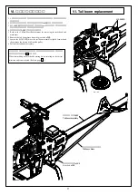
Page 58: ...brace from the pivot bolt 5X4 3 Loosen the M2 6X6CS move the tail boom assembly slightly forward and then remove the timing belt from the pulley 4 Pull out the tail boom assembly 22 When assembling e...

Page 59: ...58 3 3 1 5 Repair parts...

Page 60: ...02 2506 044 2500 082 2500 055 2521 130 0304 015 2532 049 2506 046 2500 057 2521 109 2532 039 0304 018 2505 019 2500 057 2532 029 2532 031 0304 017 2525 006 2521 109 2532 039 2525 007 2500 093 2531 001...

Page 61: ...Brg 5X 10X4H Brg 5X 10X4H thrust 2 1 680 1 600 2500 093 Brg 2X 5X2 3F ZZ 2 1 260 1 200 2500 098 Brg 2X 5X2 3ZZ 2 1 260 1 200 2505 006 M3 M3 nylon nut 10 210 200 2505 009 M2 M2 nylon nut 10 840 800 250...

Page 62: ...44 2532 033 2532 028 2532 028 0304 037 2521 112 2536 001 2521 085 2532 034 2532 039 2530 012 2536 001 2532 004 0304 038 2521 112 0403 022 2531 001 0402 014 2500 044 2532 036 2532 036 2534 013 0304 032...

Page 63: ...6 Cross member M3X26 with M2 6 hole 1 525 500 2500 044 Brg 8X 16X5ZZ 2 1 260 1 200 2500 057 Brg 3X 6X2 5F ZZ 2 1 260 1 200 2505 020 M3 M3 nylon nut thin type black 10 315 300 2506 001 FW 2X 6X0 4T 20...

Page 64: ...32 049 2531 002 2505 019 0304 004 0304 003 2500 110 2500 111 0304 022 2500 110 0304 023 0304 025 2539 023 0304 026 0304 027 0304 005 0304 002 0304 006 0304 007 2532 028 0304 020 2507 001 2509 009 2500...

Page 65: ...n case 1 2 100 2 000 Case only 0304 023 LEX LEX auto rotation shaft 1 1 575 1 500 With ring 0304 024 LEX 56T LEX main pulley 56T 1 525 500 With screws 0304 025 LEX 94T LEX main gear 94T 1 2 940 2 800...

Page 66: ...09 2532 031 0304 041 2524 001 2522 004 2524 014 2522 001 2524 001 0304 062 2522 001 2524 014 2524 016 2524 001 2522 010 2522 003 2522 021 0304 035 2534 005 2525 006 2532 031 2522 021 2522 004 2524 016...

Page 67: ...ollar 3X4X8 5F 2 525 500 2522 001 M2X16 Adjust rod M2X16 5 525 500 2522 003 M2X30 Adjust rod M2X30 5 525 500 2522 004 M2X35 Adjust rod M2X35 5 525 500 2522 005 M2X45 Adjust rod M2X45 5 525 500 2522 01...

Page 68: ...06 005 0304 044 2500 073 2505 009 2532 036 2500 054 0414 141 2509 022 0304 047 2504 029 2509 021 2521 131 2524 001 2522 001 0304 042 2522 001 2524 001 0304 046 2505 019 2500 050 0304 045 2539 015 2532...

Page 69: ...de L 54 2 420 400 0304 064 LEX LEX rudder control rod set 1 1 set 525 500 0304 065 LEX LEX tail holder 1 2 625 2 500 With screws 0414 141 Tail pitch plate boss 1 525 500 2500 050 Brg 3X 8X4ZZ 2 1 260...

Page 70: ...69 0304 060 0304 061 0304 059 2529 014 2534 004 0304 058 0304 057 2505 009 2532 048 2506 001 2505 009 0304 053 2525 007 2532 054 0304 054 2532 028...

Page 71: ...anopy 1 1 260 1 200 With screws 0304 059 LEX LEX blade support 1 420 400 0304 060 EX Lepton EX decal 1 1 260 1 200 0304 061 EX Lepton EX instruction manual 1 2 100 2 000 2505 009 M2 M2 nylon nut 10 84...

Page 72: ...OR NOR 50 F S 0 NOR NOR CH1 AIL CH2 ELE TYPE HELI SR 3 FUTABA FF9 CH3 THR CH4 RUD CH5 GYR CH6 PIT CH1 AIL CH2 ELE CH3 THR CH4 RUD CH5 GYR CH6 PIT NOR 0 75 100 100 100 0 0 0 0 100 100 75 90 90 100 0 0...

Page 73: ...0 15 INH INH 50 INH INH 82 15 INH INH 50 INH INH 82 20 INH INH 60 INH INH 100 L 1 2 3 4 5 H ST 1 ST 2 ST 3 ST 4 NORM ST 1 ST 2 ST 3 ST 4 HOLD HOLD HOLD CH6 HOLD GER HOLD RUD HOLD CH3 HOLD CH2 Pos 172...

Page 74: ...75 80 75 75 80 50 50 50 50 H L 50 50 75 75 80 75 75 80 100 90 100 100 90 100 100 90 80 100 90 80 100 100 100 100 100 100 85 100 100 N 1 2 3 4 N 1 2 3 4 N 1 EXP D R 2 3 4 N 1 2 3 SANWA STYLUS TH CURV...

Page 75: ......

Page 76: ...made to ensure that this manual is complete and correct Should there however be any oversights mistakes or omissions that come to your attention please inform us Item not withstanding we cannot be re...

Reviews: