15
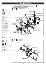
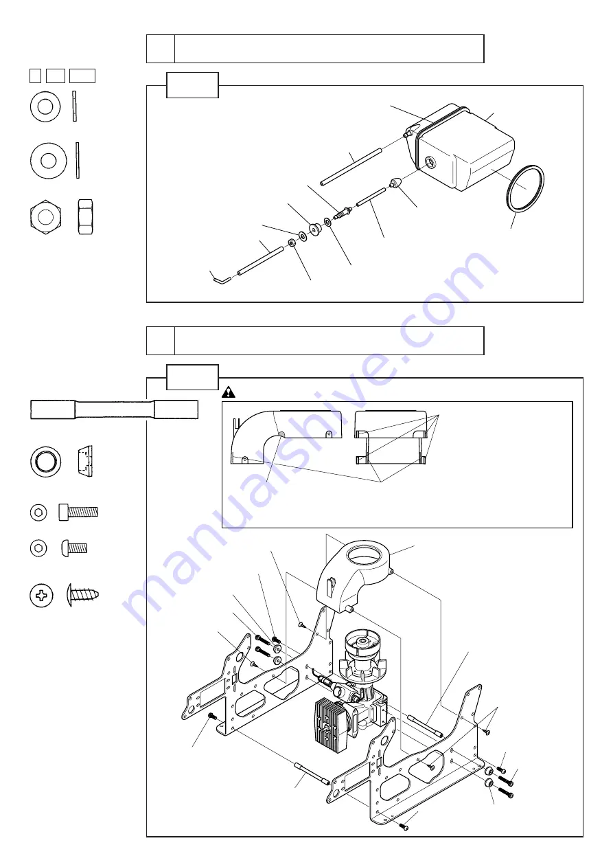
STEP 1
4
燃料タンクの組立
Assembling the fuel tank
Z ZX ZXX
M5 ナット .................................... 1
M5 nut
φ5×φ12×0.8FW ........................ 1
φ5×φ10×1FW ........................... 1
φ5×10×1FW
φ5×12×0.8FW
M5 ナット
M5 nut
燃料タンクニップル
Fuel tank nipple
燃料タンク
Fuel tank
燃料タンクオモリ
Fuel tank weight
タンク防振ゴム
Tank vibration
preventing rubber
タンク防振ゴム
Tank vibration
preventing rubber
燃料タンクキャップ
Fuel tank cap
シリコンパイプ φ3×5×150
Silicon pipe
シリコンパイプ φ2.3×3.6×75
Silicon pipe
シリコンパイプ φ3×5×90
Silicon pipe
ジョイントパイプ
Joint pipe
φ3 強化ワッシャー
φ3 Reinforcement washer
φ3 強化ワッシャー
φ3 Reinforcement washer
M3×57 クロスメンバー
M3×57 cross member
M3×57 クロスメンバー
M3×57 cross member
M3×10CS(仮組み)
(Temporarily)
M3×10CS(仮組み)
(Temporarily)
M3×6 ボタンボルト
M3×6 button bolt
M3×6 ボタンボルト
M3×6 button bolt
M3×6 ボタンボルト
M3×6 button bolt
M3×6 ボタンボルト
M3×6 button bolt
M3×8 TS トラス-2
M3×8 TS truss-2
M3×8 TS トラス-2
M3×8 TS truss-2
M3×8 TS トラス-2
M3×8 TS truss-2
クーリングファンカバー
Cooling fan cover
フレームに固定したとき、
押されて変形
する場合は、
0.5mm程度ずつ削り取っ
てください。
If these portions are deformed when
installed on the frame, cut these
portions off by 0.5 mm each.
スロットルレバーが干渉
する場合は、
切り取って
ください。
If the throttle lever interferes,
cut this portion off.
エンジンによってはエンジンヘッドが干渉することがあります。
干渉しないように削り取ってください。
Engine head may interfere with these depending on engine
types. If so, cut there portions off.
注意
Caution
M3×8 TS トラス-2 ...................... 4
M3×8 TS truss-2
M3×6 ボタンボルト..................... 4
M3×6 button bolt
M3×10CS ................................. 4
φ3 強化ワッシャー ...................... 4
φ3 Reinforcement washer
M3×57 クロスメンバー............... 2
M3×57 cross member
5
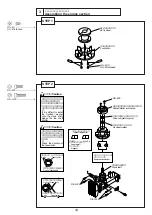
ロアーフレームの組立
Assembling the lower frame
STEP 1


