40
⑨
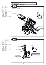
スロットルレバー
Throttle lever
サーボに付属のネジ
Screw attached to the servo
機首方向
Front side
カット
Cut
スロットル A
フルハイ位置
Throttle A
Full high
スロットル B
アイドリング位置
Throttle B
Idling
スロットル C
エンジンストップ位置
Throttle C
Engine stop
13mm
ロッ
ク
M2×6 CS
サーボホーン
Servo hone
EX φ5ボール
EX φ5 Ball
M2ナット
M2 Nut
A
B
C
S
スロットルサーボ
Throttle servo
モードⅠ
MODEⅠ
モードⅡ
MODEⅡ
モードⅠ
MODEⅠ
モードⅡ
MODEⅡ
モードⅠ
MODEⅠ
モードⅡ
MODEⅡ
モードⅠ
MODEⅠ
モードⅡ
MODEⅡ
モードⅠ
MODEⅠ
モードⅡ
MODEⅡ
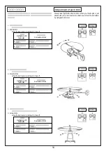
④ エンコンサーボホーンの位置を調整します。サーボホーンのスプラインで角度を合わします。Sを中心にA
とBは同じ角度にします。
④ Adjust the position of the engine-control servo horn. Adjust the angle using the spline of the servo horn. The angles A
and B from the point S should be equal.
⑤ サーボホーンにEXφ5Ballを取付ます。
⑤ Install EX #phi#5 ball to the servo horn.
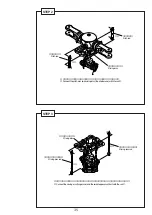
⑦ 送信機のエンコンスティックをフルハ
イにした時、スロットルレバーがフル
ハイになるように、エンコンロツトの
長さを調整します。
⑦ Adjust the length of the engine control rod
so that the throttle lever is at Full High
when the engine control stick of the
transmitter is adjusted to Full High.
⑧ 送信機のエンコンスティックをスロー
にし、エンコントリムをスローにした
とき、スロットルレバーが完全にス
ロー側になるように、送信機
フタバ ATV
JR TRVL ADJ
サンク EPA
スローの数値で合わせてください。
標準値 70%〜80%
⑧ Adjust the transmitter values (FUTABA
ATV, JR TAJ, SANK EPA) so that the
throttle lever is precisely at Slow position
when the engine control stick of the
transmitter is at Slow and the engine
control trim is adjusted to Slow.
Standard value: 70% - 80%
⑥ エンコンロッドを取付ます。
⑥ Install the engine control stick.
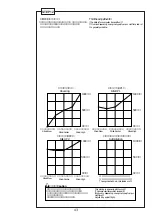
送信機のスティックとトリムとエンコンサーボの動作関係が
下図のようになること。
The relation among the transmitter stick, trim, and engine-control
servo shall be as shown below.
STEP 9-2


