background image

53

トラッキング調整

Rotor blade tracking

トラッキングの調整は危険ですので、機体から5m程離れて行ない
ます。

Keep at least 5m distance between you and your helicopter.

Caution

注意

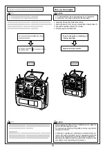
1. Gradually raise the throttle stick towards a HIGH setting until the

helicopter is just about to taking off.

2. Carefully watch the tracking of the rotor blade trips. If both rotor

blades are the same track, it is all right. However, if the tracks of
one blade is higher/lower than the other, it is necessary to adjust
the tracking.

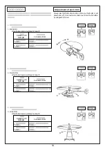
3. To adjust tracking, remove the rod end of the collective pitch con-

trol.

4. Shorten the rod end of the blade whose track is higher than the

other. Elongate the rod end of the blade which track is lower. (Turn
each rod end one or two times)

1. スロットルスティックをゆっくりとハイ側に動かし機体が浮かび上

がる直前に止めます。

ローターの回転面を真横から見ます。

2. ローターの軌跡をよく見てください。

2 枚のローターが同じ所を通っていれば OK ですが、上下にずれて

いる場合、トラッキング調整が必要です。

3. トラッキング調整はピッチロッドのロッドエンドを回して調整しま

す。

A:軌跡の高いブレード側の

ピッチロッド

B:軌跡の低いブレード側の

ピツチロツド

→ ロツドの長さを伸ばす

→ ロッドの長さを縮める

トラッキングがずれていると振動の原因になります。確実に合う

まで何度も繰り返します。

トラッキング調整を行ったあとでもう一度、ホバリングでのピッ

チ角が約 5.5 ゜となっているか確認してください。

Incorrect tracking causes vibration of the helicopter. After tracking
adjustment, confirm if the pitch of blade at the hovering is 5.5 ゜
approx.

Caution

注意

ピッチロッド

Pitch rod

Summary of Contents for Shuttle RG

Page 1: ...ion as can result in serious harm depend ing of the circumstances involved P 1 P 1 P 1 5 P 6 P 7 P 8 P 9 P 10 46 P 47 57 P 58 P 59 P 60 75 INTRODUCTION P 1 CONTENTS P 1 ALWAYS FOLLOW THESE RULES FOR S...

Page 2: ...htened properly and that there is no part that is damaged or improperly attached or an other part or place in a condi tion that would adversely affect the right of the helicopter Alwayscheckticbesuret...

Page 3: ...use of the danger of burns do not touch the engine or the muf fler after starting or immediately after stopping the engine 1 Be sure to check the following items Check each section of the helicopter a...

Page 4: ...e Trying to teach yourself is extremely danger ous 2 Check to be sure that there are no loose or missing nuts and bolts 3 Check to be sure that there is no play or slack in the linkage rods or control...

Page 5: ...licopter lifts off adjust the tracking of each rotor Verifying the tracking should be done from a distance of 5 meters from the helicopter 7 Should unusual vibrations or noise occur while in flight la...

Page 6: ...number as that section Refer to the column on the left hand side of the page to check the part quantities 1 2 Before assembling the model USING METHOD OF THIS MANUAL The reconfiguration of this model...

Page 7: ...1mm 3mm 4mm 3mm 12mm Collar C 5 8 5 5 Thrust bearing Brg 6 12 Button bolt M3 8 3mm 10mm 3mm 8mm 3mm 12mm 3mm 10mm 2mm 4 5mm 4mm 4mm 8mm 4mm 2 5mm 8mm 5mm 3mm 7mm 6mm 5 5mm 8mm 5mm 12mm 6mm 3mm 8mm Sy...

Page 8: ...luded in this kit Starter shaft Radio set The following transmitters are recommended Futaba FF8 H JR X3810 SANWA Stylus Gyro 12V 12V Battery for engine starter Not required for the engine with recoil...

Page 9: ...9 Main rotor blade Stabilizer blade Tail rotor blade Main rotor head Cabin Tail boom brace Horizontal stabilizer Vertical stabilizer Tail boom NAME OF EACH PART...

Page 10: ...elevator arm M3 15 M3 15 cross member M3 15 M3 15 cross member M2 12CS M2 12CS M3 6 M3 6 button bolt M3 6 M3 6 button bolt M3 6 M3 6 button bolt M3 6 M3 6 button bolt M3 3SS M3 3SS 3 4 5 0 5FW Brg 3 7...

Page 11: ...X 5 ball EX 5 EX 5 ball EX 5 EX 5 ball EX 5 EX 5 ball EX 5 EX 5 ball EX 5 EX 5 ball Brg 3 8 4 Brg 3 8 4 Brg 3 8 4 Brg 3 8 4 M2 6CS M2 6CS M2 6CS M2 6CS M2 6CS M2 6CS S3 5 5 S3 5 5 EX 5 If the boss at...

Page 12: ...9 Brg holder as shown in the figure on the left Tighten the screw so that frame is positioned vertically with horizontal line Elevator lever Note Direction of elevator lever looking from above Nose Ri...

Page 13: ...n bolt M3 33 2 M3 33 cross member STEP 3 M4 4SS 1 3 4 5 0 5FW 1 4 6 0 5FW 1 M3 25 2 M3 25 button bolt C 4 6 2 1 C 3 7 4S 2 R Collective pitch lever R Collective pitch shaft L Collective pitch lever L...

Page 14: ...nut part of engine Fly wheel washer SE SE shaft starter clutch shoe Check the direction of the taper collar Caution Caution If it is difficult to install the flywheel washer onto the crank shaft pleas...

Page 15: ...mporarily M3 10CS Temporarily M3 6 M3 6 button bolt M3 6 M3 6 button bolt M3 6 M3 6 button bolt M3 6 M3 6 button bolt M3 8 TS 2 M3 8 TS truss 2 M3 8 TS 2 M3 8 TS truss 2 M3 8 TS 2 M3 8 TS truss 2 Cool...

Page 16: ...5FW L 64 Starter shaft L 64 C 3 7 14 C 3 7 14 Mechanical plate 15 26 Cross member block 15 26 Apply grease C 3 7 14 M3 25 M3 25 button bolt M3 6 M3 6 button bolt M3 26 M3 26 cross member M3 26 M3 26 c...

Page 17: ...echanical plate support To prevent interference between fuel tank and tapping screw fix 2 pieces of double sided adhesive tapes between them Fuel tank 10 20 Fix 2 pieces of double sided adhesive tapes...

Page 18: ...Skid foot 10mm M3 5SS M3 M3 nylon nut M3 M3 nylon nut 3 9 1FW M3 5SS 3 9 1FW Antenna guide tube M3 5SS Never over tighten M3x5SS screws Caution M3 15CS 8 Installation of the landing gear STEP 1 M3 5SS...

Page 19: ...FW Auto rotation drive shaft P 12 O P 12 O ring grease up Auto rotation torque limiter M3 M3 nylon nut M3 3SS Fix the mast lock with the mast pulled up Mast lock M3 3SS 9 Installation of the main gear...

Page 20: ...M3 12 button bolt 3 4 5 0 5FW 3 4 5 0 5FW 3 4 5 0 5FW Brg 3 7 3ZZ Brg 3 6 2 5FZZ Brg 3 6 2 5FZZ EX 5 EX 5 ball EX 5 EX 5 ball with stand M3 6 M3 6 button bolt M3 12 M3 12 button bolt M2 6CS M2 6CS Cen...

Page 21: ...zer bar M3 3SS M3 3SS Stopper Adhere Stabilizer blade A B B A Note Balance the Stabilizer blade and adjust by winding tape etc around the lighter side Stabilizer blade and Stabilizer control arm must...

Page 22: ...bolt E M2 6CS 3 D Pivot bolt D E Pivot bolt E M2 6CS EX 5 EX 5 ball with stand EX 5 EX 5 ball with stand D E 5 Install pivot bolt D pivot bolt E and 5 ball radius pin to the swash plate body r 7mm r 5...

Page 23: ...Pivot bolt E Attach the radius arm to longer pivot bolt Elevator lever Swash plate Parallel Install the elevator lever and swash plate in parallel 90 Radius block Center hub 4mm 14 Combination of the...

Page 24: ...e timing belt Do not fix the screws too tight Caution S3 5 5 S3 5 5 M2 6CS 5 7 0 1FW M3 6 M3 6 button bolt M3 6 M3 6 button bolt M3 6 M3 6 button bolt M3 6 M3 6 button bolt M3 5SS Caution Guide pully...

Page 25: ...e of the shaft M3 5SS Pass the tail pulley shaft through tail pitch plate Install tail housing to tail pulley and fix it to the leveled side of the shaft with M3 5SS Caution Check the position of the...

Page 26: ...f pipe to the boss on the inside of tail unit case M4 10PH M3 22CS Tail boom pipe Vertical fin mounting band Vertical fin 3 5 6 8 3 5 6 8 Collar M3 nut 16 Assembling the tail boom STEP 1 M3 22CS 2 M4...

Page 27: ...5mm Keep a clearance of approximately 0 5 mm at the upper and lower of the starter shaft Caution Tail pilley 8T Drive pilley R Set the groove of tail pipe to the boss on the inside of main frame R Ad...

Page 28: ...zontal stabilizer Brace Tail boom brace terminal 2 Screw the tail boom brace terminal into the brace Assemble two tail boom braces so that the same side of the tail boom brace terminals at both ends f...

Page 29: ...el tank M3 28CS Use the screws attached to the muffler for the assembly kit Fuel filter Not included Fuel tank Caburetor 19 Installation of the muffler STEP 1 M3 28CS 2 Only the sub assembly compo nen...

Page 30: ...Servo attaching nut Spacer 2 6 7 5 0 5FW M2 6 14TS 2 Prepare 2 sets Cut 20 Installation of the servos STEP 1 STEP 2 M2 6 14TS 4 2 6 7 5 0 5FW 4 2 Servo attaching nut M2 6 14TS 4 2 6 7 5 0 5FW 4 Instal...

Page 31: ...o attaching nut Spacer 2 6 7 5 0 5FW M2 6 14TS M2 6 8CS STEP 3 STEP 4 M2 6 14TS 2 2 6 7 5 0 5FW 2 1 Servo attaching nut M2 6 8CS 2 M2 6 14TS 2 2 6 7 5 0 5FW 2 1 Servo attaching nut M2 6 8CS 2 Installa...

Page 32: ...nut M2 6 14TS 2 6 7 5 0 5FW M2 6 14TS 2 6 7 5 0 5FW STEP 5 STEP 6 M2 6 14TS 8 2 6 7 5 0 5FW 8 4 Servo attaching nut Installation of the elevator servo Gyro Double side adhesive tape Switch Switch pla...

Page 33: ...r and servo Then confirm the direction of rotation of the sticks and the servo When the direction of rotation is incorrect change the reverse switch of the transmitter and set it to move as designated...

Page 34: ...m 21mm 90mm 75mm 2 5mm 2sets Mixing arm rod X 2sets X type lever Elevator torque lever X 2sets X type lever Aileron lever Aileron lever Swash rod 2sets Elevator rod 2sets Aileron rod Pitch rod Throttl...

Page 35: ...ing arm Pitch rod Connect the pitch arm and mixing arm the shorter one with the rod Mixing arm rod Mixing arm Mixing arm rod Connect the mixing arm longer one and the swash upper pivot bolt with the r...

Page 36: ...in parallel Connect the aileron lever and swash plate with rod so that the swash plate is horizontal with front view when the X lever is vertical X X type lever Elevator torque lever X X type lever E...

Page 37: ...0 A B Adjust the length of the rod A so that the X lever and the servo horn are at the right angle when the transmitter stick is in neutral and the trim is in neutral then adjust the length of the rod...

Page 38: ...13mm 13mm Approx Front side Front view A B MODE MODE 90 Cut X 90 A B Adjust the length of the rod A so that the X lever and the servo horn are at the right angle when the transmitter stick is in neut...

Page 39: ...ervo hone M2 M2 Nut Pitch rod M2 6 CS EX 5 EX 5 Ball EX 5 EX 5 Ball with stand Screw attached to the servo Front side MODE MODE Cut 8mm Horizontal Horizontal Position of transmitter stick 50 Adjust th...

Page 40: ...X 5Ball Install EX phi 5 ball to the servo horn Adjust the length of the engine control rod so that the throttle lever is at Full High when the engine control stick of the transmitter is adjusted to F...

Page 41: ...M2 Nut Perpendicular to the tail boom pipe initial setting The position changes depending on the hovering rpm Adjust it by actual flight M2 Pass the rudder control rod through the guide and out of th...

Page 42: ...Center Stiek High Stiek Slow Stiek Center Stiek High MODE Caution This setting is a general pitch curve The computer transmitter is used It may vary depending on engine types fuels or mufflers Adjust...

Page 43: ...Slow Stiek Center Stiek High The engine shall be in idle status or off Caution This setting is a general pitch curve The computer transmitter is used It may vary depending on engine types fuels or muf...

Page 44: ...2 holes M2 M2 Nut Wind shield M2 6 M2 6 Truss M3 8TS M3 8TS Truss 2 Make 2 holes Cabin damper bush Cabin Cabin Cabin damper bush Inside Cabin damper rubber Cabin damper rubber 2 Install the guide rail...

Page 45: ...45 23 Attachment of the Decal STEP 1 R Cabin Horizontal stabilizer Vertical stabilizer...

Page 46: ...event them from being loosened by vibration Firmly tighten all bolts untill they protrude through the nylon section If the bolt is not firmly tightened a main blade may be lost while running This is v...

Page 47: ...porting your model to the airfield always place it in the car so that it does not bounce or fall over Should the model not be fastened securely it may become damaged and as a result safety and flight...

Page 48: ...re tight Check if the batteries of your radio are sufficiently charged Caution 1 Use only GLOW fuel for model engines Do not use gasoline nor kerosine to operate this engine GLOW fuel is a powerful an...

Page 49: ...quency and inform him yours Interference from another model on the same frequency may cause dangerous mishan dling of your model Caution Check ON Turn on the transmitter ON Turn on the receiver and gy...

Page 50: ...and Fit the starter shaft into the starter and rotate Remove the starter once the engine has started 4 Holding the rotor head check that the engine stops when the throttle trim is set to its lowest le...

Page 51: ...h 8 Check the fuel filter Is it clean 9 Is there too much fuel flowing into the engine Remove the engine plug Turn the engine with starter to exhaust it of fuel Symptom 2 Engine stops after running fo...

Page 52: ...When stopping the main rotor for maintenance etc place the palm of the hand against the yoke Do not wear gloves during this operation as they may become entangled in the rotor Continuing to operate yo...

Page 53: ...owever if the tracks of one blade is higher lower than the other it is necessary to adjust the tracking 3 To adjust tracking remove the rod end of the collective pitch con trol 4 Shorten the rod end o...

Page 54: ...ut to take off 2 2 Elevator trim When the helicopter is just about to take off 3 3 Aileron trim When the helicopter is just about to take off Inclination of helicopter Correction of trim a Turns to a...

Page 55: ...should not be flown too high One of the basic elements of correct and safe helicopter flight is HOOVERING So take time to become accomplished at hovering 1 Hoovering is to fly the helicopter at a fix...

Page 56: ...turning flight so that you can turn a helicopter in either direc tion Place yourself at the center of the intended turning circle of the helicopter and move the hovering position forward slowly Gradua...

Page 57: ...source Always take used nickel cadmium batteries to a shop that participates in a recycling program Trouble on flying Cleaning and storage Disposal and recycling Symptom Cause Countermeasure Adjust th...

Page 58: ...lace the main mast Check the main rotor blade The main rotor blade is balanced Balance the main rotor blade Balance on the tail rotor blade Balance the tail rotor blade Check the rotor head Replace th...

Page 59: ...000 250 1 000 1 05 250 1 300 530 214 726 8614 TEL 0847 41 6780 FAX 41 8902 TEL 0847 41 7400 FAX 41 9361 5 H T M T 2 1 9 4 1 1 05 726 8614 530 214 TEL0847 41 7400 0402 543 SF 1 800 800 190 0402 544 SF...

Page 60: ...060 0403 209 0403 262 2530 009 0403 207 0403 202 2539 010 2506 004 2500 045 0402 622 0402 623 0402 624 2500 057 2525 002 2532 031 2539 017 0402 284 2539 010 2525 005 2532 028 2500 086 2500 057 0402 28...

Page 61: ...ring spindle 2 0403 209 400 190 Pitch arm 2 0403 212 1 600 270 Stabilizer blade 1 0403 262 5 000 390 GT GT blade holder 2 2500 045 1 200 130 Brg 6 15 5 ZZ 2 2500 057 1 200 130 Brg 3 6 2 5F ZZ 2 2500 0...

Page 62: ...06 019 2530 005 0402 573 2531 002 0402 014 0402 268 2525 005 2530 004 2530 005 2532 031 0402 572 2500 080 0402 260 2500 080 2533 012 2508 003 2500 048 0402 591 2505 006 2506 016 2529 005 2532 008 0402...

Page 63: ...03 219 500 270 77T Main gear 77T 0404 023 300 90 Radius arm 2500 048 1 500 190 Brg 12 16L Brg 12 16L one way 2 11 8 Grooved parallel pin 2 11 8 EX 5 EX 5 ball 1 5 E 1 5 E ring O P 12 O ring P 12 D 5 5...

Page 64: ...64 0400 004 2506 005 0402 620 0402 518 0402 715 2500 080 0402 520 0402 700 0402 522 0402 254 0402 257 0402 517 2500 081 0402 603 0402 023...

Page 65: ...SF Clutch bell 0402 522 400 90 SF 8T SF Drive pulley 8T 0402 593 3 800 130 SE 20T SE Drive pulley 20T 0402 603 5 800 390 SE SE Muffler 0402 620 700 130 SE L 68 SE Stater shaft L 68 Brg 8 19 6 ZZ Brg...

Page 66: ...57 2500 094 2511 023 2505 005 2524 014 2522 028 2522 005 2522 021 2522 004 2522 015 2500 094 2539 018 2500 050 2521 069 0402 706 0404 625 2506 019 0402 708 2531 002 2524 001 0403 235 2505 006 2506 005...

Page 67: ...2 2521 057 200 130 4 6 3 Collar 4 6 3 2 2521 039 200 130 4 6 2 Collar 4 6 2 2 2521 069 300 130 3 7 4S Collar 3 7 4S 2 2511 017 500 190 M3 33 Cross member M3 33 2 2511 023 500 190 M3 15 Cross member M3...

Page 68: ...86 0402 703 2536 001 2539 017 2505 002 0402 702 2511 006 0402 045 2539 018 2539 017 0402 515 0403 308 2505 015 2511 003 2511 003 2521 070 2521 070 0402 701 0403 246 0402 704 0402 705 0404 635 2532 012...

Page 69: ...M3 Nylon nut 2505 002 200 130 M3 M3 Nut 0404 635 500 130 3T Servo mount spacer 3T 0403 308 700 270 Vibration preventing rubber ring 0403 246 500 190 Tail boom holder 10 2505 015 300 130 W W type nut f...

Page 70: ...92 0402 577 2524 004 2500 057 2506 019 2539 015 0402 601 2521 049 0402 594 0402 597 2506 005 2505 006 2511 002 2531 002 0402 595 2506 021 0402 585 0402 602 0402 575 2539 017 0402 576 2521 046 0402 235...

Page 71: ...0 90 M3 M3 Nylon nut 20 2506 005 100 130 FW 4 6 0 5 20 2506 019 100 90 FW 3 4 5 0 5T 5 2506 021 400 90 FW 5 7 0 1T 5 2524 001 250 90 M2 M2 Rod end 5 2525 002 1 000 130 EX 5 EX 5 ball 10 2531 002 300 9...

Page 72: ...72 2506 010 2532 038 2523 007 0403 254 0403 259 2505 006 2531 001 0402 532 0402 535 0402 713 0402 714 2505 001 0402 282 0402 281 2536 001 0402 682 0404 547 2532 015...

Page 73: ...00 390 Assy Landing gear Assy white 0402 532 390 Skid Pipe aluminum 0402 533 2 000 800 390 Assy Landing gear Assy black 0402 535 1 000 390 Skid Pipe Black 20 1 1 2505 001 200 90 M2 M2 nut 0404 547 500...

Page 74: ...13 026 2513 025 2513 027 2513 024 0402 587 0403 266 0402 267 2522 009 0402 610 2525 005 2506 004 2532 003 0402 609 0402 006 2500 068 0402 608 2532 010 2524 001 2505 006 2506 007 0406 003 2534 004 0406...

Page 75: ...ing gear set 0402 591 190 SE 77T SE Main Gear 77T 0402 606 1 800 3 800 1 050 MRB MRB Conversion set 0403 266 3 500 390 GT GT Landing gear Pre Painted white Aluminum 1 1 1 1 1 1 1 1 2513 025 3 200 270...

Page 76: ...76 98 01 13 3 1 P76...

Page 77: ...77...

Page 78: ...at this manual is complete and correct Should there however be any oversights mistakes or omissions that come to your attention please inform us Item not withstanding we cannot be responsible for even...

Reviews: