background image


HIROSE ELECTRIC CO.,LTD.


ETAD-T0652-00


5

/6 

FORM HC0011-9-2 

0

(6) 

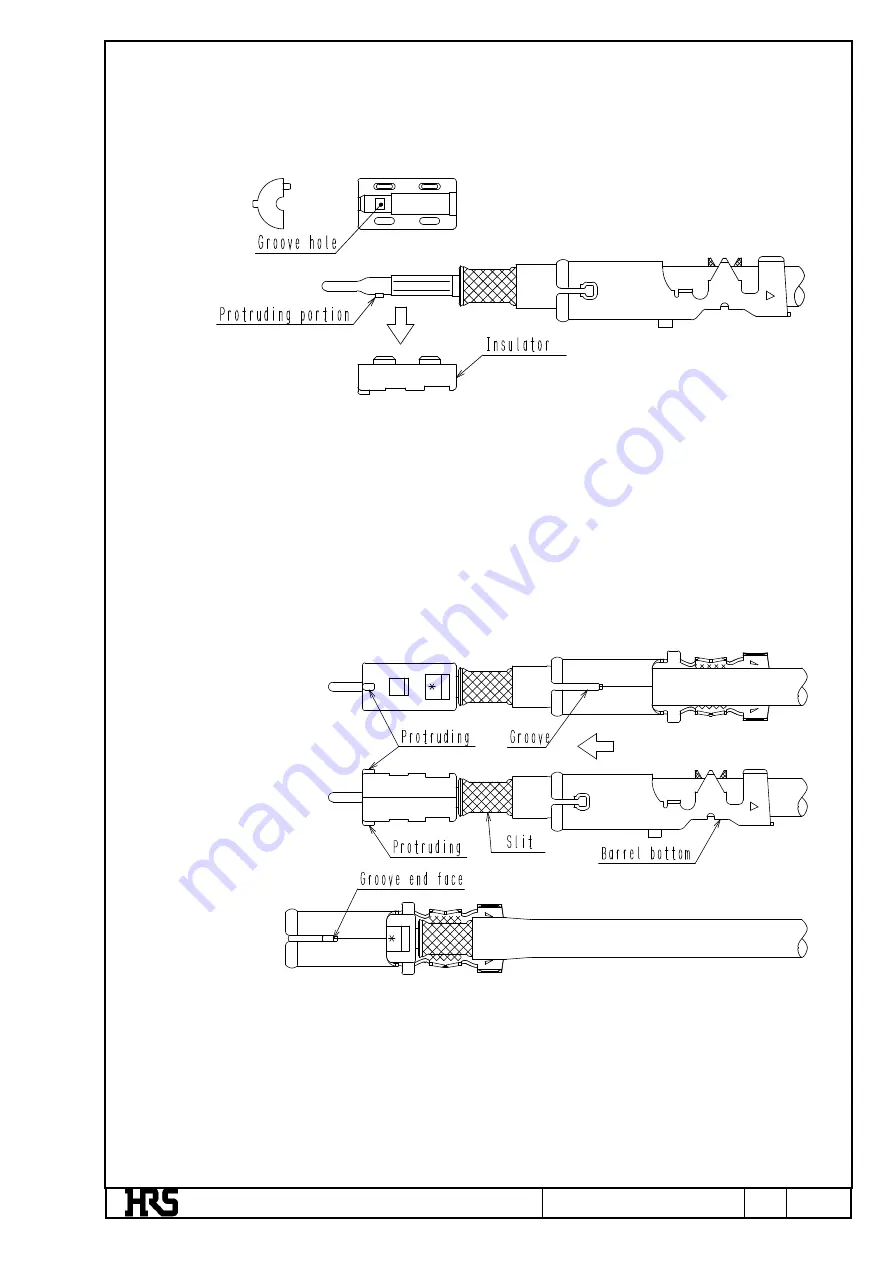
 Put the above contact unit onto the insulator, and fit another insulator onto the contact unit. 

Note: 1. 

Put the protruding part of the center contact onto the groove hole. 

Note: 2. 

Pull the cable at a force of approximately 4.9N and check that the contact unit will not be 

pulled out. 


(7) 

Assemble the outer contact to the insulator. 

Note: 1. 

Check that the direction of the outer contact is correct as shown in the illustration below. 

Make  sure  that  the  left  and  right  dents  on  the  insulator  coincide  with  the  grooves  of  the 

outer contact in coaxial direction (i.e., the slit of the outer ferrule coincide in position with 

the barrel bottom of the outer contact). 

Note: 2. 

Insert the cable until the insulator is stopped by the groove end face of the outer contact. 


Jul.1.2022 Copyright 2022 HIROSE ELECTRIC CO., LTD. All Rights Reserved.

Summary of Contents for GT16GM Series

Page 1: ...T MAKI 17 10 25 TITLE GT16GM SERIES IN LINE WIRE HARNESS INSTRUCTION MANUAL APPROVED KI HIROKAWA 17 05 24 CHECKED MO OKADA 17 05 24 DESIGNED MING JIANG 17 05 23 WRITTEN MING JIANG 17 05 23 TECHNICAL SPECIFICATION ETAD T0652 00 1 1 6 FORM HC0011 9 1 HIROSE ELECTRIC CO LTD Jul 1 2022 Copyright 2022 HIROSE ELECTRIC CO LTD All Rights Reserved ...

Page 2: ...r Model HRS No GT16G PC CL766 0047 3 3 Outer contact Model HRS No GT16G 1 6 2 9PC CL766 0048 6 4 Outer ferrule Model HRS No GT16G 1 5DHQS L CL766 0111 0 5 Contact ferrule Model HRS No GT16G FR CL766 0028 9 6 Housing Model HRS No GT16GM 1P HU CL766 0050 8 GT16GMN 1PP HU CL766 0051 0 Jul 1 2022 Copyright 2022 HIROSE ELECTRIC CO LTD All Rights Reserved ...

Page 3: ...heath will be aligned together Make sure that the cable is not deformed 3 Pay utmost attention not to damage the cut edge of the core conductor dielectric material or outer conductor 2 Use the dedicated jig and crimp the center contact Note 1 Refer to The Crimp Condition Table for the crimp height Note 2 Refer to The Crimp Quality Standard Sheet for the crimp work standards 3 Put the cable into th...

Page 4: ...g part of the center contact and insert the outer ferrule Note 3 Insert the outer ferrule until the step of the outer ferrule comes to the edge of the sheath Note 4 Pay attention not to pull the outer conductor into the sheath when inserting the outer ferrule 5 Use the dedicated jig and insert the contact ferrule from the mating side of the center contact until the contact ferrule comes in contact...

Page 5: ...ut 7 Assemble the outer contact to the insulator Note 1 Check that the direction of the outer contact is correct as shown in the illustration below Make sure that the left and right dents on the insulator coincide with the grooves of the outer contact in coaxial direction i e the slit of the outer ferrule coincide in position with the barrel bottom of the outer contact Note 2 Insert the cable unti...

Page 6: ...dards Note 3 Confirm that the insulator is fixed by the lance of the outer contact 9 Insert the outer contact into the housing Note 1 Coincide the protruding part of the outer contact with the groove of the housing and insert the outer contact Note 2 Insert the outer contact until the position of the outer contact is fixed by the lance of the housing 10 Harness work completed 0 4 Jul 1 2022 Copyri...

Reviews: