background image

5

Contents

Version 1.0  03/06

1 Introduction

 . . . . . . . . . . . . . . . . . . . . . . . . . . . . . . . . . . . . . . . . . . . . . . . . . . . . . . . . . . . . . .

7

2 Half duplex operation

 . . . . . . . . . . . . . . . . . . . . . . . . . . . . . . . . . . . . . . . . . . . . . . . . . . . . . .

9

3 Tristate recognition through permanent high

 . . . . . . . . . . . . . . . . . . . . . . . . . . . . . . . . .

11

4 Network topologies

 . . . . . . . . . . . . . . . . . . . . . . . . . . . . . . . . . . . . . . . . . . . . . . . . . . . . . . . .

13

4.1

Line topology without redundancy . . . . . . . . . . . . . . . . . . . . . . . . . . . . . . . . . . . . . . . . . . . . . . . . . 13

4.2

Star distributor  . . . . . . . . . . . . . . . . . . . . . . . . . . . . . . . . . . . . . . . . . . . . . . . . . . . . . . . . . . . . . . . . 14

4.3

Network range  . . . . . . . . . . . . . . . . . . . . . . . . . . . . . . . . . . . . . . . . . . . . . . . . . . . . . . . . . . . . . . . . 15

4.4

Cascadability and data rate  . . . . . . . . . . . . . . . . . . . . . . . . . . . . . . . . . . . . . . . . . . . . . . . . . . . . . . 15

5 Installation

 . . . . . . . . . . . . . . . . . . . . . . . . . . . . . . . . . . . . . . . . . . . . . . . . . . . . . . . . . . . . . . .

17

5.1

Installation guidelines  . . . . . . . . . . . . . . . . . . . . . . . . . . . . . . . . . . . . . . . . . . . . . . . . . . . . . . . . . . . 17

5.2

Use in North America  . . . . . . . . . . . . . . . . . . . . . . . . . . . . . . . . . . . . . . . . . . . . . . . . . . . . . . . . . . . 19

5.3 

Installing procedure  . . . . . . . . . . . . . . . . . . . . . . . . . . . . . . . . . . . . . . . . . . . . . . . . . . . . . . . . . . . . 19

5.4

Installing repeater  . . . . . . . . . . . . . . . . . . . . . . . . . . . . . . . . . . . . . . . . . . . . . . . . . . . . . . . . . . . . . . 20

5.5

Installing terminating resistor and pull-up/pull-down resistors  . . . . . . . . . . . . . . . . . . . . . . . . . . . 21

5.6

Connecting the optic bus cables  . . . . . . . . . . . . . . . . . . . . . . . . . . . . . . . . . . . . . . . . . . . . . . . . . . 21

5.7

Connecting the electric bus cables  . . . . . . . . . . . . . . . . . . . . . . . . . . . . . . . . . . . . . . . . . . . . . . . . 22

5.8

Connecting the function ground  . . . . . . . . . . . . . . . . . . . . . . . . . . . . . . . . . . . . . . . . . . . . . . . . . . 22

5.9

Connecting the operating voltage supply  . . . . . . . . . . . . . . . . . . . . . . . . . . . . . . . . . . . . . . . . . . . 23

5.10 Checking the LED indicators  . . . . . . . . . . . . . . . . . . . . . . . . . . . . . . . . . . . . . . . . . . . . . . . . . . . . . 23

6 Bus configurations

 . . . . . . . . . . . . . . . . . . . . . . . . . . . . . . . . . . . . . . . . . . . . . . . . . . . . . . . .

25

6.1

BITBUS . . . . . . . . . . . . . . . . . . . . . . . . . . . . . . . . . . . . . . . . . . . . . . . . . . . . . . . . . . . . . . . . . . . . . . 25

6.2 

Configuration of other bus systems  . . . . . . . . . . . . . . . . . . . . . . . . . . . . . . . . . . . . . . . . . . . . . . . . 26

7 Help with problems

 . . . . . . . . . . . . . . . . . . . . . . . . . . . . . . . . . . . . . . . . . . . . . . . . . . . . . . . .

27

7.1

LED displays . . . . . . . . . . . . . . . . . . . . . . . . . . . . . . . . . . . . . . . . . . . . . . . . . . . . . . . . . . . . . . . . . . 27

7.2 

Troubleshooting  . . . . . . . . . . . . . . . . . . . . . . . . . . . . . . . . . . . . . . . . . . . . . . . . . . . . . . . . . . . . . . . 28

7.3 

Problem reporting  . . . . . . . . . . . . . . . . . . . . . . . . . . . . . . . . . . . . . . . . . . . . . . . . . . . . . . . . . . . . . 28

7.4 

Contact address . . . . . . . . . . . . . . . . . . . . . . . . . . . . . . . . . . . . . . . . . . . . . . . . . . . . . . . . . . . . . . . 29

8 Technical data

 . . . . . . . . . . . . . . . . . . . . . . . . . . . . . . . . . . . . . . . . . . . . . . . . . . . . . . . . . . . .

31

Contents

Summary of Contents for 943 893-321

Page 1: ...System OZD 485 G12 BAS DA STAT 3 1 2 RT K1 K1 K1 K1 RT Port 1 Manual Universal RS 485 Fiberoptic Repeater OZD 485 G12 BAS Hirschmann Simply a good Connection...

Page 2: ...rol GmbH All Rights Reserved Note We wish to point out that the content of this manual is not part of a previous or existing agreement consent or legal relationship or shall not amend same All the lia...

Page 3: ...he care and use of appropriate safety equipment in accordance with the current stan dards of safety engineering trained in providing first aid General safety instructions D This device is operated by...

Page 4: ...d by Hirschmann are permitted to open the housing Underlying norms and standards The devices fulfill the following norms and standards EN 61000 6 2 2001 Generic standards Immunity for industrial envir...

Page 5: ...cy energy and if not instal led and used in accordance with the instruction manual may cause harmful interference to radio communicati ons Operation of this equipment in a residential area is likely t...

Page 6: ...4 Version 1 0 03 06...

Page 7: ...nstalling procedure 19 5 4 Installing repeater 20 5 5 Installing terminating resistor and pull up pull down resistors 21 5 6 Connecting the optic bus cables 21 5 7 Connecting the electric bus cables 2...

Page 8: ...6 Version 1 0 03 06...

Page 9: ...BAS Repeaters The housing consists of two plastic sections and a front panel made of metal It can be mounted on a DIN rail Ports The Repeater has three independent ports which in turn consist of a tr...

Page 10: ...epeater itself Transmission speed The RS 485 Fiberoptic Repeater OZD 485 G12 BAS supports all data rates from 0 to 1 5 MBit s NRZ Network range The permissible network range for the line or star topol...

Page 11: ...hat at any given time only one device can access the bus like in master slave operation Access procedures where there is a risk of collisions such as CAN are not permissible In half duplex mode consec...

Page 12: ...2 Half duplex operation 10 Version 1 0 03 06...

Page 13: ...wire lead terminated by a characteristic impe dence and additional pull up pull down resistors is replaced e g PROFIBUS During the idle phase a logical high level positive volt age between terminals...

Page 14: ...3 Tristate recognition through permanent highHigh 12 Version 1 0 03 06...

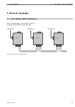
Page 15: ...ogy without redundancy Terminal device s bus segment Port 1 K 1 Port 3 Port 2 Terminal device s bus segment Port 1 K 1 Port 3 Port 2 Terminal device s bus segment Port 1 K 1 Port 3 Port 2 This network...

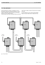
Page 16: ...ice s bus segment Terminal device s bus segment The star distributor is made by coupling two or more OZD 485 G12 BAS via the electrical interfaces Lines or other star distributors can be connected to...

Page 17: ...increase in the bit duration distortion due to jitter in the optical transmission link depends on the number of OZD 485 G12 BAS in the transmission link Determining the cascadability To determine the...

Page 18: ...4 Network topologies Subkapitel 16 Version 1 0 03 06...

Page 19: ...fects must be reduced to a minimum The structural design and correct connection of bus lines as well as the interference suppression of switched induct ances play a major role in limiting interference...

Page 20: ...load circuits The wires 24 VDC and 0 V should be twisted together Standard recommendations for the arrangement of devices and cables EN 50174 2 contains recommendations for arranging devices and cable...

Page 21: ...end of the line If necessary Install pull up pull down resistors as long as the device is located at the end of the line Connecting the optical bus cables Connecting the electrical bus cables Connecti...

Page 22: ...t the bus and power supply cabling Connect the optical fiber line before mounting the repeater as this simplifies the procedure Mount the repeater on the DIN rail To do this hang the top latch of the...

Page 23: ...nal block terminating resistor and pull up pull down resistors Verbinden Sie die einzelnen Repeater ber ein Duplex LWL Kabel mit BFOC 2 5 ST Steckverbindern Beachten Sie die maximale L nge der LWL Kab...

Page 24: ...connection must be connected to an equipotential rail in the switch cabinet The equi potential rails of the switch cabinets which are con nected to one another by means of an electrical RS 485 bus cab...

Page 25: ...pin terminal block on the top of the repeater You can input the voltage supply via the terminal 24 V of the terminal block The minus connection is indicated by 0 V 5 9 Connecting the operating voltag...

Page 26: ...5 Installation 24 Version 1 0 03 06...

Page 27: ...cribed in the standard 6 Bus configurations 6 1 BITBUS 3 8 5 120 470 470 K1 RT RT RT RT K1 Bitbus contact connections 3 120 470 470 8 5 K1 K1 Bitbus contact connections 7 6 1 Bitbus contact connection...

Page 28: ...chapter 6 1 please clarify which termination the bus system has and derived from this the type of tristate identification The OZD 485 G12 BAS only sup ports RS 485 bus systems that have a high level...

Page 29: ...1 yellow off DA STAT 2 green yellow off DA STAT 3 green yellow off Possible causes Repeater operating correctly Supply voltage interrupted Internal device error Data received at port 1 No input signa...

Page 30: ...physical interface correspond to the standard RS 485 3 Does the bus access procedure of the bus system used ensure that at any given time only one partici pant can access the bus Warning Access proced...

Page 31: ...act address for technical support Hirschmann Automation and Control GmbH Stuttgarter Strasse 45 51 72654 Neckartenzlingen Germany Allemagne Tel 49 1805 14 1538 Fax 49 7127 14 1551 E Mail hac support h...

Page 32: ...7 Help with problems 30 Version 1 0 03 06...

Page 33: ...fiber G 50 125 20 dBm in fiber G 62 5 125 16 dBm Receiver sensitivity 30 dBm Transmission distance with 3 dB system reserve line attenuation with fiber G 50 125 3 0 dB km 0 2 3 km 10 dB with fiber G 6...

Page 34: ...condensing IEC 60068 2 30 Air pressure during operation up to 2000 m 795 hPa transport and storage up to 3000 m 700 hPa Contamination level 2 Mechanical ambient conditions Vibrations 3 to 9 Hz 3 5 mm...

Page 35: ......

Page 36: ...Control GmbH Stuttgarter Strasse 45 51 72654 Neckartenzlingen Germany Allemagne Tel 49 1805 14 1538 Fax 49 7127 14 1551 E Mail hac support hirschmann de Internet http www hirschmann com 039 554 001 E...

Reviews: