36
BAT-F, BAT-Rail, BAT54, BAT300
Release 02 07/10
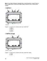
Note: Insert the terminators supplied into unused sockets in order to avoid
radio signals from one WLAN module being received by the other WLAN
module.
BAT54-F
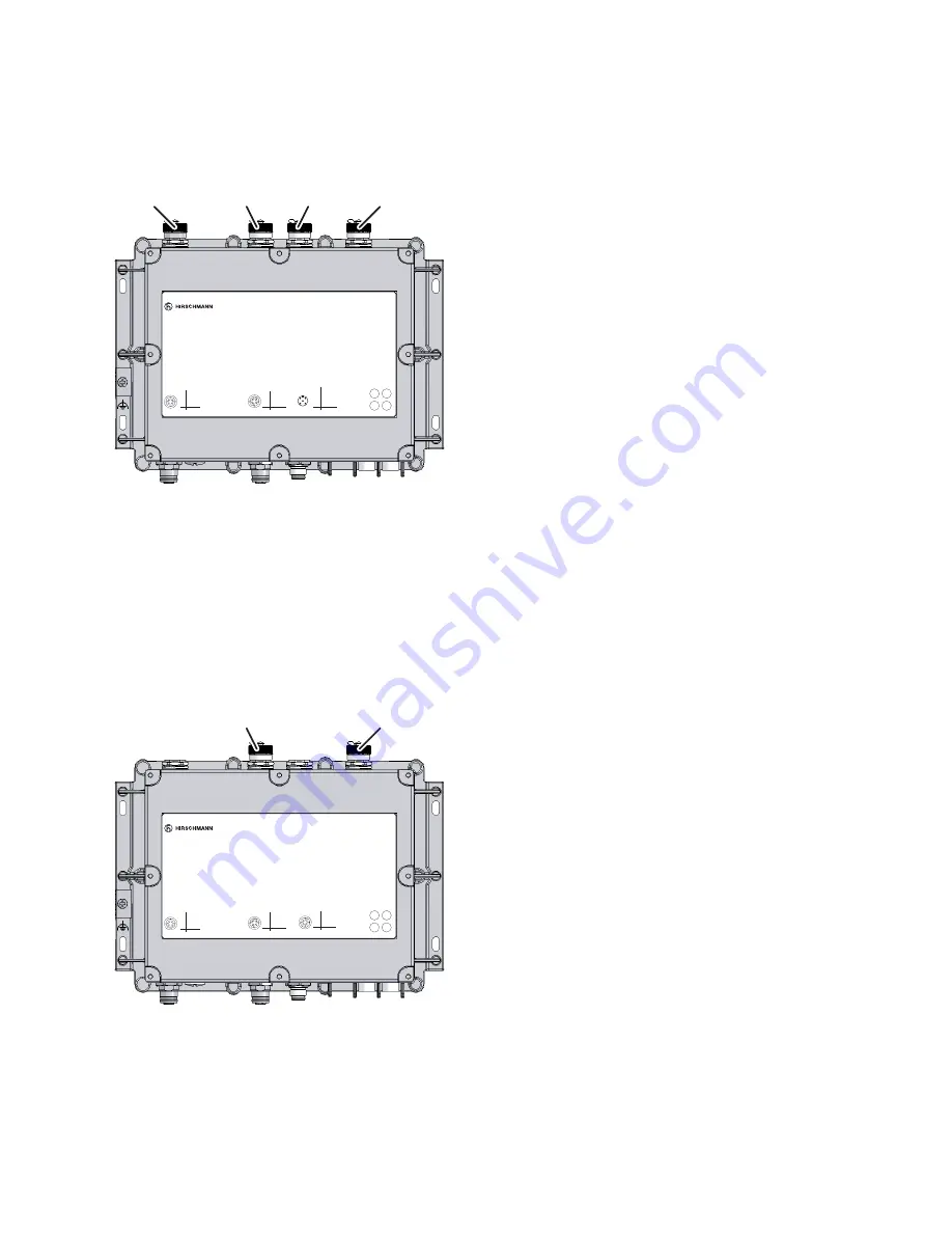
Figure 8: Connections for external antennas on BAT54-F
1 - Main 1
2 - Main 2
3 - AUX 1
4 - AUX 2
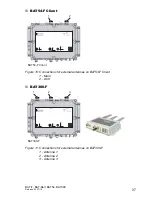
BAT54-F Single
Figure 9: Connections for external antennas on BAT54-F Single
1 - Main
2 - AUX
1
2
3
4
4
1
2
3
1
2
3
4
Pin
TX
RX
N.C.
GND
Function
V.24
1
2
3
4
Pin
TD+
RD+
TD-
RD-
Function
4
1
2
3
Ethernet
4
3
2
1
5
1
2
3
4
5
Pin
+24V DC
0 V
0 V
+24V DC
N.C.
Function
Reset
Power
LED
Main 1
Main 2
AUX 1
AUX 2
BAT54-F
IP67 WLAN Access Point
LS/DA
P
WLAN
2
WLAN
1
Uin : 24 VDC
Uin : 48 VDC
CLASS 2
CLASS 2
Iin : 400 mA
Iin : 170 mA (PoE)
BAT54-F
4
1
2
3
1
2
3
4
Pin
TX
RX
N.C.
GND
Function
V.24
1
2
3
4
Pin
TD+
RD+
TD-
RD-
Function
4
1
2
3
Ethernet 2
Reset
LED
Main
AUX
BAT54-F Single
IP67 WLAN Access Point
Uin : 24 VDC
Uin : 48 VDC
CLASS 2
CLASS 2
Iin : 420 mA
Iin : 170 mA (PoE)
1
2
3
4
Pin
TD+
RD+
TD-
RD-
Function
4
1
2
3
Ethernet 1
WLAN
P
LS/DA
2
LS/DA
1
1
2
BAT54-F Single

