24
BAT54-F
Release 12/07
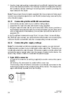
Use the main and auxiliary connections of one WLAN module if you want
to use the diversity function. The diversity function increases the connec-
tion quality by always sending or receiving via the antenna providing the
best contact to the client.
Note:
Please insert the terminators supplied into the sockets not being used
in order to avoid radio signals from one WLAN module being received by the
other WLAN module.
2.2.5
Connecting LAN and WLAN connections
Connect the access point to your LAN for configuration.
Assemble the network cable with the M12 plug supplied.
Plug the network cable into the LAN connection of the device, and into a
free network connection socket on your local network (or into a free sock-
et on a hub/switch). Alternatively, you can also connect the device to a
separate PC.
In the "Dual-Band Industrial Access Point / Access Client / Access Bridge
BAT54-Rail" user manual, you will find further information for connecting the
LAN and WLAN connections with the corresponding remote terminals.
2.2.6
Connecting the supply voltage
Note:
For redundant and failure-resistant power supply, you can connect
multiple power sources in any combination at the same time. The device au-
tomatically selects the power supply. If the power supply currently active fails
and another power supply takes over the supply of power to the device, the
device may reboot in order to reactivate the power supply.
5-pin M12 connector
A 5-pin M12 connector (A coding, supplied) is used to connect the power
supply.
On delivery, the connection is sealed with a cover cap.
The housing of the M12 frame connector is electrically connected to the
function ground and to the metal housing of the device. The supply volt-
age is electrically isolated from the housing.
4
3
2
1
5
Pin
1
2
3
4
5
Function
+24V DC
0 V
0 V
+24V DC
N.C.
Power
Summary of Contents for BAT54-F
Page 40: ...40 BAT54 F Release 12 07 ...
Page 42: ......


