22
Installation BXS
Release 01 04/2022
1.6
Pin assignments
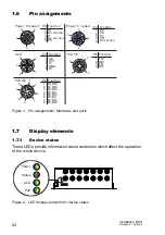
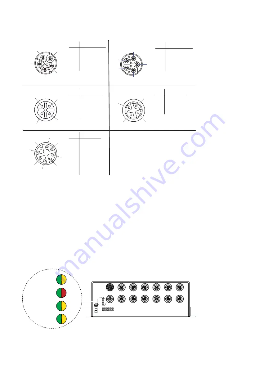
Figure 1: Pin assignments: Interfaces and ports
1.7
Display elements
1.7.1
Device status
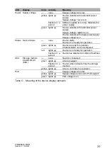
These LEDs provide information about conditions which affect the operation
of the whole device.
Figure 2: LED display elements for device status
1 Uin
2 CC1
3 D-
4 GND
5 D+
Pin Function
1
2
3
4
5
ACA
Function
Pin
1 P+
2
3 P-
4
5 PE
Do not use
Do not use
Function
Pin
1 Bl_DB+
2 Bl_DB-
3 Bl_DA+
4 Bl_DA-
5 Bl_DC+
6 Bl_DC-
7 Bl_DD-
8 Bl_DD+
1
2
7
4
3
5
6
8
Port GE
Pin
1 TD+
2 RD+
3 TD-
4 RD-
Function
1
2
3
4
5
1
2
3
4
5
Power “K”-coded
Function
Pin
1 P1+
2
3 P1-
4
5
P2-
P2+
Do not use
Power “L”-coded
1
2
4
3
Port FE
Power
Status
ACA
PoE
Summary of Contents for BXS
Page 50: ......


