6
z
Warning!
The EAGLE mGuard equipments are
designed for operation with a safety
extra-low voltage.Thus, they may
only be connected to the supply vol-
tage connections and to the signal
contact with PELV circuits or
alternatively SELV circuits with the
voltage restrictions in accordance
with IEC/EN 60950.
– Voltage supply
: Redundant voltage sup-
plies are supported. Both inputs are
decoupled. There is no load distribution.
With redundant supply, the power pack
supplies the EAGLE mGuard only with the
higher output voltage. The supply voltage
is electrically isolated from the housing.
You can choose between DC or AC vol-
tage when connecting the supply voltage.
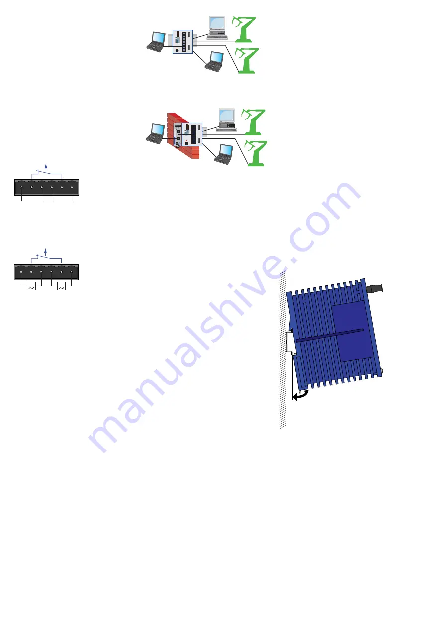
You use the +24V und 0V pins to connect
the AC voltage (see Fig. 4 and 5).
Fig. 4: Pin configuration of 6pin terminal
block, connecting DC voltage
Fig. 5: Pin configuration of 6pin terminal
block, connecting AC voltage
– Indicator contact:
The indicator contact is used to supervise
the functions of the EAGLE mGuard and
thus facilitates remote diagnosis.
Contact interrupt indicates the following
by means of a potential-free indicator
contact (relay contact, closed circuit):
– the failure of at least one of the two
supply voltages.
– a permanent fault in the EAGLE mGuard
(internal 3,3 V DC voltage, supply vol-
tage 1 or 2 < 9.6 V, ...).
– the faulty link status of at least one port.
The indication of the link state on the
EAGLE mGuard can be masked on a
port-by-port basis using the manage-
ment software.
State of delivery: there is no link test.
– self test error
Note:
In the case of the voltage supply
being routed without redundancy, the
EAGLE mGuard indicates the failure of a
supply voltage. You can prevent this
message by feeding in the supply voltage
through both inputs.
Ground connection
The EAGLE mGuard is grounded via a sepa-
rate screw connection.
FAULT
G
18...30 VAC
G
18...30 VAC
+24V(P1)
0V
0V
+24V(P2)
FAULT
9,6...60 VDC
9,6...60 VDC
+24V(P1)
0V
0V
+24V(P2)
+
-
-
+
2. Configuration
To get access to the EAGLE mGuard, you
act as follows (device in the state of
delivery):
䡺
To configure the EAGLE mGuard, start a
web browser with https capability on
the PC connected to the trusted port (
k
)
(e. g. MS Internet Explorer V. 5.0 or
higher).
䡺
Connect the untrusted port (
g
) to your
network.
䡺
In the address field of the web browser
you enter the following address:
https://1.1.1.1/
Result: The configuration connection to the
EAGLE mGuard is being built up. A security
note is displayed.
䡺
Quit the security note with “Yes”.
䡺
For login you enter:
– Login: admin
– Password: private
(Observe the use of small and capital
letters!)
Result: The administrator website of the
EAGLE mGuard is displayed.
䡺
Configure the device.
Alternatively you can carry through the IP
configuration for the MCT mode via the
HiDiscovery protocol. You will find the
HiDiscovery software on the CD ROM which
is included in the scope of delivery.
Note:
If the configuration connection to the
EAGLE mGuard is not built up, you will find
detailed information in the „Manual EAGLE
mGuard Management – Industrial ETHER-
NET Firewall/VPN System“.
3. Assembly, startup procedure
and dismantling
Before installation and startup please pay
attention to the security notes on the pages
2 and 3. With the following steps you set
the EAGLE mGuard into operation:
3.1 UNPACKING, CHECKING
䡺
Check whether the package was deliver-
ed complete (see scope of delivery).
䡺
Check the individual parts for transport
damage.
z
Warning!
Use only undamaged parts!
3.2 ASSEMBLY
The equipment is delivered in a ready-to-
operate condition. The following procedure
is appropriate for assembly:
䡺
Pull the terminal block off the EAGLE
mGuard and wire up the supply voltage and
indicator lines.
䡺
Fit the EAGLE mGuard on a 35 mm
standard bar to DIN EN 50 022.
䡺
Attach the upper snap-on slide bar of
the EAGLE mGuard to the standard bar and
press it down until it locks in position.
䡺
Connect the device to the local network
or the local PC which is to be protected
(
k
).
䡺
Connect the socket for connection to the
external network (
g
), e. g. the Internet.
(Via this network the connctions to the
remote device or the remote network
are realized.)
Notes:
– The front panel of the EAGLE mGuard is
grounded via a separate ground connec-
tion.
– Do not open the housing.
– The shielding ground of the twisted pair
lines which can be connected is electrical-
ly connected to the front panel.
Fig. 8: Assembling the EAGLE mGuard
3.3 STARTUP PROCEDURE
You start up the EAGLE mGuard by connec-
ting the supply voltage via the 6-pin termi-
nal block. Lock the terminal block with the
locking screw at the side.
3.4 DISMANTLING
䡺
To take the EAGLE mGuard off the
ISO/DIN rail, insert a screwdriver horizontal-
ly under the housing into the locking slide,
pull it (without tipping the screwdriver)
downwards and lift the EAGLE mGuard
upwards.
EAGLE
2
1
STATUS
P
2
1
LS/DA
2
1
+24V (P1)
FA
U
LT
+24V (P2)
0V
0V
V.24
Aufkleber MAC-Adresse
IP-ADDRESS
g
k
x
FAULT
R
V.24
Fig. 6: Configuration before installing the
EAGLE mGuard (example)
Fig. 7: Configuration with firewall after
installing the EAGLE mGuard (example)


