background image

RS20/RS30

Release 1.0 09/05

41

4   


Further support

U

Technical questions and training courses

In the event of technical queries, please talk to the Hirschmann contract 


partner responsible for looking after your account or directly to the 


Hirschmann office. You can find the addresses of our contract partners 
on the Internet:


http://www.hirschmann.com

Our support line is also at your disposal:

D

Tel. +49(1805) 14-1538

D

Fax +49(7127) 14-1551

Answers to Frequently Asked Questions can be found on the 
Hirschmann internet site www.hirschmann.com/faq

U

Hirschmann Competence Center

In the longterm, product excellence alone is not an absolute guarantee of 
a successful project implementation. Comprehensive service makes a 
difference worldwide. In the current scenario of global competition, the 
Hirschmann Competence Center stands head and shoulders above the 
competition with its comprehensive spectrum of innovative services:

D

Consulting incorporates comprehensive technical advice, from system 
evaluation through network planning to project planning.

D

Training offers you an introduction to the technological fundamentals, 
product briefing and user training with certification.

D

Support ranges from commissioning through the standby service to 
maintenance concepts.

With the Competence Center, you firmly rule out any compromise: the 
client-specific package leaves you free to choose the service compon-
ents that you will use. 


Internet: http://www.hicomcenter.com

Summary of Contents for MACH 4002 48+4G

Page 1: ... DA LS DA LS DA LS DA LS DA LS DA LS DA P 1 LS DA 2 3 4 5 6 7 8 1 4 7 2 5 8 3 6 M4 FAST 8SFP P 1 2 3 4 5 6 7 8 1 4 7 2 5 8 3 6 P P1 P2 P3 P4 RM RL1 RL2 FAN RUN L D FDX 1000 AN TP FO RING PORT STBY LED TEST 2 1 1 2 3 4 LED MEDIA SLOTS M4 AIR SLOT PORT USB V 24 5 1 5 2 5 3 5 4 6 1 6 2 6 3 6 4 6 5 6 6 6 7 6 8 6 9 6 10 6 11 6 12 6 13 6 14 6 15 6 16 SELECT LED MACH 4002 48 4G FAULT RL2 LS DA LS DA LS D...

Page 2: ... use The performance features described here are binding only if they have been expressly guaranteed in the contract This publication has been created by Hirschmann Automation and Control GmbH according to the best of our knowledge Hirschmann reserves the right to change the contents of this manual without prior notice Hirschmann can give no guarantee in respect of the correctness or accuracy of t...

Page 3: ...18 2 1 1 Unpacking and checking 18 2 1 2 Assembling the media modules 18 2 1 3 Assembling the SFP modules if required 19 2 1 4 Assembling the power supply unit on the back of the device 20 2 1 5 Assembling the slide in power units to the power unit chassis if required 20 2 1 6 Setup or installation of the device in a 19 rack 21 2 1 7 Grounding the device 21 2 1 8 Assembling the power unit chassis ...

Page 4: ...1 Disassembling the media modules 33 2 4 2 Disassembling the SFP modules 33 3 Technical data 34 General data 34 Interfaces 35 EMV and stability 35 Power consumption power output 36 Scope of delivery 37 Order numbers Product name 37 Asseccories 38 4 Further support 41 ...

Page 5: ...connected to the supply voltage shown on the type plate V The DC modules M4 VDC 300W are designed for operation with a safety extra low voltage Thus they may only be connected to the supply voltage connections with PELV circuits or alternatively SELV circuits with the voltage restrictions in accordance with IEC EN 60950 V For the case where the DC modules M4 VDC 300W are opera ted with external po...

Page 6: ...Board invalidates the guarantee V The device has to be mounted in a horizontal position V After the device being switched off the fan will continue to rotate a few moments Never reach into the rotating fan V The internal workings of the chassis are not for users Do not reach in side a switched on device because of the danger caused by high en ergy densities V When fully equipped with media modules...

Page 7: ... that have received appropriate training should operate this device or work in its immediate vicinity The personnel must be ful ly familiar with all of the warnings and maintenance measures in these operating instructions V Correct transport storage and assembly as well as careful operation and maintenance are essential in ensuring safe and reliable operation of this device V Only use undamaged pa...

Page 8: ... its conducting bag whenever it is not in the chassis ESD protective field kits are available for working with electrostatic sensi tive devices You can find more information about devices vulnerable to electrostatic fields in DIN IEC 47 Sec 1330 February 1994 Edition and DIN EN 100 015 U Note on the CE marking The devices comply with the regulations contained in the following European directives 8...

Page 9: ...egulations These requirements are designed to provide sufficient protection against interference where the device is being used in a business environment The device creates and uses high frequencies and can radiate same and if it is not installed and used in accordance with this operating manual it can cause radio transmission interference The use of this device in a living area can also cause int...

Page 10: ... configure the System Location and System Name D configure the network address range and SNMP parameters D save the configuration on the Switch D simultaneous configuration of several Switches D configure the relevant ports to be displayed red if there is no link state With the network management software Industrial HiVision you increase net work security in industrial applications D Early Warning...

Page 11: ...imple configuration with only one additional connection The diagnosis LEDs for displaying the operating parameters provide a quick overview It can be easily managed via a Web browser via Telnet with a management software product such as F or locally on the switch V 24 interface The MACH4002 is composed of a Switch with media modules that can be plugged into it It allows you to construct switched I...

Page 12: ...i a m o d u l e 1 s l i d e i n m o d u l e m e d i a m o d u l e 3 s l i d e i n m o d u l e m e d i a m o d u l e 5 s l i d e i n m o d u l e m e d i a m o d u l e 2 s l i d e i n m o d u l e m e d i a m o d u l e 4 s l i d e i n m o d u l e m e d i a m o d u l e 6 i n t e g r a t e d b a c k o f d e v i c e p o w e r s u p p l y u n i t e x t c o n n e c t o r 3 t o M 4 P O W E R e x t c o n n ...

Page 13: ...21 USB AutoConfiguration Adapter D A V 24 socket for the network management connection D Two signal contacts that are integrated on one socket together The LED display block on the left side of the Basic Board informs you about the status of the device You use the SELECT button to define the meaning of the LED displays At the front left of the base chassis of the MACH 4002 there is a replaceable f...

Page 14: ...or redundant power supply D M4 S 48VDC 300W 2 inputs for redundant power supply See Order numbers Product name on page 37 Note The slide in power units of the power unit chassis cannot be used for the switch chassis 1 2 2 M4 POWER power unit chassis The M4 POWER power unit chassis enables redundant power supply It has three slots for slide in power units The slide in power units can be replaced du...

Page 15: ...ant power supply D M4 P 48VDC 300W 2 inputs for redundant power supply see Order numbers Product name on page 37 Note The slide in power units of the switch chassis cannot be used for the power unit chassis 1 3 Fan plug in unit M4 AIR The M4 AIR fan input is located on the left of the front side of the MACH 4002 chassis The fan can be replaced during running operation see Replacing the M4 AIR fan ...

Page 16: ... apply to the active port You can use the SELECT button to test the TP or FO connections For the order numbers of the SFP plug in modules see Order numbers Product name on page 37 1 4 2 16 Fast ETHERNET ports There are 16 10 100BASE TX ports ports number 6 1 to 6 16 for connecting power unit segments on the right side of the Basic Board These ports are RJ 45 connections USB V 24 5 1 5 2 5 3 5 4 6 ...

Page 17: ...module has eight 100BASE FX ports SFP slots for mounting SFP modules The following SFP plug in modules Fast ETHERNET SFP transceiver are available to you for the M4 FAST 8 SFP media module D M FAST SFP MM LC D M FAST SFP SM LC D M FAST SFP SM LC D M FAST SFP LH LC For the order numbers of the SFP plug in modules see Order numbers Product name on page 37 P 1 LS DA 2 3 4 5 6 7 8 M4 8TP RJ45 LS DA LS...

Page 18: ...minal block for signal contact D Connecting the supply voltage startup procedure D Connecting the data lines D Replacing the fan plug in unit M4 AIR if required 2 1 Assembling the device 2 1 1 Unpacking and checking V Check whether the package was delivered complete see State of delivery on page 31 V Check the individual parts for transport damage 2 1 2 Assembling the media modules The device has ...

Page 19: ...far as it will go into the desired slot see Fig step 2 V Make sure that there is a good connection between the multiple plugs of the media modules and the female multipoint of the system bus V Insert the media module as far as it will go into the desired slot by closing the blue insertion catches see Fig step 3 V Screw the two knurled screws in the front panel of the media module flush with the fr...

Page 20: ...o the power unit chassis if required Replace a defective slide in power supply unit only with a plug in power sup ply unit of the same type V Disconnect the power cord V Loosen the eight screws used to fasten the plug in power supply unit in the chassis and pull the unit out of the chassis or remove the covering pla te of the power supply unit slot V Slide the new plug in power supply unit into th...

Page 21: ...ack and data cables to be connected from the front Note For rack mounting use chassis runners 2 1 7 Grounding the device The device is grounded via the power supply connectors Note The shielding ground of the connectable twisted pairs lines is connec ted to the front panel as a conductor When the device is being operated by means of the 230 120 VAC power supply unit it is grounded via the safety p...

Page 22: ...inuous malfunction in the device D The defective link status of at least one port With the device the indi cation of link status can be masked by the management for each port Link status is not monitored in the delivery condition D The loss of Redundancy guarantee D Error during self test The following conditions are reported in stand by mode D Control cable disrupted D Control cable shorted D Par...

Page 23: ...strictions in accordance with IEC EN 60950 The external supply voltage can be connected redundantly see Voltage supply on page 14 Both inputs are uncoupled With redundant supply the power supply unit alone supplies the device with the higher output voltage The supply voltage is electrically isolated from the housing The DC modules M4 VDC 300W are grounded via a connector of the 3 pin DC socket Swi...

Page 24: ...e HIPER Ring ports 100 Mbit s full duplex The socket housings are electrically connected to the front covering Fig 6 Pin assignment of a TP TX interface in MDI X mode RJ45 socket U 10 100 1000 Mbit s twisted pair connection 1000 Mbit s twisted pair connection 1000 MBit s twisted pair ports RJ45 sockets enable the connection of terminal devices or independent net work segments in compliance with th...

Page 25: ... to MM ports U 1 Gbit s F O connection 1 Gbit s F O ports SFP slots enable the connection of terminal devices or independent network segments in compliance with the IEEE 802 3 2000 ISO IEC 8802 3 2000 1000BASE SX or 1000BASE LX standard These ports support D autonegotiation D full duplex mode State on delivery autonegotiation Note Make sure that you conncet LH ports only to LH ports SX ports only ...

Page 26: ...U Assembly of M4 AIR V Disassemble the fan plug in unit which is to be replaced as described above V Slide the new fan plug in unit into the chassis along the subracks abo ve and below as far as it will go V Make sure that there is a good connection to the multipoint plug of the plug in fan unit the female multipoint connector of the system bus V Screw the two knurled screws in the front panel of ...

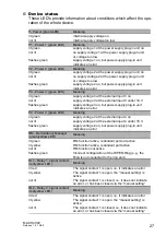
Page 27: ...supply plug in unit indicates an error P4 Power 4 green LED Meaning lit green supply voltage 4 at the external input 4 on not lit supply voltage 4 at the external input 4 under 18 V flashes green supply voltage 4 on but power supply plug in unit indicates an error RM Redundancy Manager green yellow LED Meaning lit green RM function active redundant port not active lit yellow RM function active red...

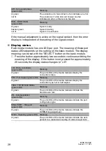
Page 28: ... least one fan indicates an error or there is no fan slot RUN BOOT RUN green LED Meaning lit green System ready flashes green System booting not lit System in reset state L D Data Link status green LED Meaning lit green The port LEDs of the media modules display the connection status FDX Full duplex green LED Meaning lit green The port LEDs of the media modules display the connection type full or ...

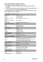
Page 29: ...lay the media type All display status LEDs green LEDs Meaning Running licht Initialization phase after restart 1 2 green LEDs Meaning Service LEDs RUN 1 Display memory operations of the Auto Configuration Adapter ACA Meaning flashing alternatively Error in teh memory operation LEDs flashing synchronously 2 times per second Loading the configuration from the ACA LEDs flashing synchronously 1 time p...

Page 30: ... Meaning not lit Half duplex is active lit green Full duplex is active 1 to 8 1000 green yellow LED Meaning not lit 10 Mbit s is active lit green 100 Mbit s is active lit yellow 1000 Mbit s is active 1 to 8 AUTONEG green yellow LED Meaning lit green Autonegotiation is active 1 to 8 TP FO twisted pair fiber optic green yellow LED Meaning lit yellow Fiber optic has been selected The port LEDs of the...

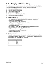
Page 31: ...looks for the IP address using DHCP D Password for management user password public read only admin password private read and write D V 24 data rate 9 600 baud D Ring redundancy off D ETHERNET ports Link status is not evaluated signal contact D Optical 100 Mbit ports 100 Mbit full duplex All other ports autonegotiation D Redundancy manager switched off D Stand by coupling off U USB interface The US...

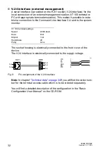
Page 32: ...ctrically connected to the front cover of the device The V 24 interface is electrically connected to the supply voltage Fig 8 Pin assignment of the V 24 interface Note In chapter Technical data on page 34ff you will find the order num ber for the terminal access cable which is to be ordered separately You will find a detailed description of the configuration in the Basic Configuration User Manual ...

Page 33: ...rom the slot by pulling the blue insertion catches see Fig steps 1 and 2 V Pull the media module out of the slot see Fig step 3 V Close the slot with a covering panel V Screw the four knurled screws in the covering panel flush with the frame of the chassis 2 4 2 Disassembling the SFP modules V Pull the SFP module on the opened lock out off the socket V Close the SFP module with the protective cap ...

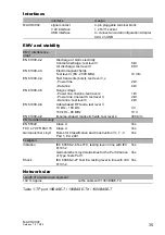
Page 34: ... 24VDC 300W M4 S 48VDC 300W 1 8 A 230 VAC max 4 2 A 110 VAC max 21 0 A 24 VDC maximum 10 1 A 48 VDC maximum M4 P AC DC 300W M4 P 24VDC 300W M4 P 48VDC 300W 1 8 A 230 VAC max 4 2 A 110 VAC max 21 0 A 24 VDC maximum 10 1 A 48 VDC maximum Switch on current M4 S AC DC 300W M4 P AC DC 300W typ 40 A at 265 VAC and cold start typ 40 A at 265 VAC and cold start Overload current protection at input non cha...

Page 35: ...e line line test level 2 Power line line earth test level 3 Data line test level 3 1 kV 2 kV 2 kV EN 61000 4 6 Cable based RF faults test level 3 10 kHz 150 kHz 150 kHz 80 MHz 3 V 10 V EN 61000 4 9 Impulse shaped magnetic fields test level 4 300 A m EMV emitted immunity EN 55022 Class A Yes FCC 47 CFR Part 15 Class A Yes Germanischer Lloyd Rules for Classification and Construction VI 7 3 Part 1 Ed...

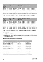
Page 36: ...dB km 800 MHz km LX LC SM 1310 nm 1 50 125 µm 0 11 dB 0 550 m 1 0 dB km 800 MHz km SX LC MM 850 nm 62 5 125 µm 0 7 5 dB 0 275 m 1 0 dB km 500 MHz km LX LC SM 1310 nm 1 62 5 125 µm 0 11 dB 0 550 m 1 0 dB km 500 MHz km LX LC SM 1310 nm 9 125 µm 0 11 dB 0 20 km 0 4 dB km 3 5 ps nm km LH LC LH 1550 nm 9 125 µm 6 22 dB 8 72 km 0 25 dB km 19 ps nm km LH LC LH 1550 nm 9 125 µm 15 32 dB 60 120 km 0 25 dB ...

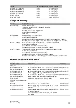
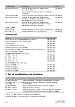
Page 37: ...er unit chassis 300W User manual installation Cable for AC connection for AC supply Connector for each DC connection for DC supply Power supply cable for connecting power unit chassis to switch chassis Product name Description Order no Chassis MACH4002 48 4G Layer2 Professional Switch Chassis 48 4G incl slide in fan unit without power supply with Layer2 Professional software 943 859 101 MACH4002 4...

Page 38: ...1 001 Terminal cable 943 301 001 4 pin terminal block 50 units 943 845 004 Netzmanagement software HiVision 943 471 100 Netzmanagement software Industrial HiVision operator edition 943 156 xxx OPC server software HiOPC 943 055 001 Gigabit ETHERNET SFP transceiver M SFP SX LC 943 014 001 M SFP LX LC 943 015 001 M SFP LH LC 943 042 001 M SFP LH LC 943 049 001 Fast ETHERNET SFP transceiver M FAST SFP...

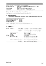
Page 39: ... Certifications actual state see www hirschmann com Switch Latency 1000 MBit s Layer 2 3 5 µs typical Layer 3 4 5 µs typical 100 MBit s Layer 2 4 5 µs typical Layer 3 5 5 µs typical 10 MBit s Layer 2 19 µs typical Layer 3 20 µs typical MAC address table up to 8000 entries Static address entries up to 100 entries in RM mode 0 unicast entries VLAN VLAN ID 1 up to 3966 Number of VLANs max 256 simulta...

Page 40: ...40 MACH 4002 Release 1 0 10 05 ...

Page 41: ...absolute guarantee of a successful project implementation Comprehensive service makes a difference worldwide In the current scenario of global competition the Hirschmann Competence Center stands head and shoulders above the competition with its comprehensive spectrum of innovative services D Consulting incorporates comprehensive technical advice from system evaluation through network planning to p...

Page 42: ... ...

Reviews: