background image

3.3 Connection of electrical bus lines

35

3 Setting Up

OZD FIP G3 …    Version 3.2  08/07

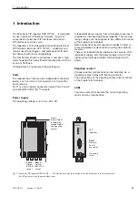
The FIP repeater should only be supplied with a
regulated 

safety extra-low voltage 

to IEC 950 /

EN 60 950 / VDE 0805 of +24 V -20% to max. +48 V
+10%.

To enhance operational reliability, a redundant supply
from various sources is provided. The operating
voltages can be supplied in two ways:

via terminal  +24 V/48 V of the terminal block

via terminal  +24 V/48 V* of the terminal block

The common negative connection in the middle of the
terminal block is indicated by ”0 V“.

The two voltages can have any (even different) values
within the specified limits of +24 V/+48 V.

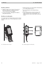
If no signaling contact lines are connected to the
terminal block (see 3.5):
Secure the terminal block by screwing on the flange.

3.4 Connection of power supply

6 / data +

7 / data –

8 / n.c.

9 / n.c.

n.c.

n.c.

n.c.

n.c.

n.c.

/ 1

/ 2

/ 3

/ 4

/ 5

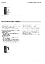
Fig. 9: Port 1 - assignment of Sub-D connector

Only bus lines to the French Standard NF-C 46-604
should be used as the FIP bus line.

The electrical FIP interface (Port 1) is a 9-pole Sub-D
connector (male).
The pin assignment complies with the French
Standard NF-C 46-604

A line which is fitted with 9-pole Sub-D connectors
(female) should be used to connect data terminal
equipment. Max. length 100 m.

Termination
OZD FIP G3: The electrical port is not internally termi-
nated. The external termination must be provided in
or on the connector of the bus line in accordance with
the French Standard NF-C 46-604.
OZD FIP G3 T: The electrical port is internally termi-
nated. Therefore no termination steps are necessary .

The bus connection plug should be secured using
screws.

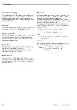
3.3 Connection of electrical bus lines

z

Warning!

The shielding of the Sub-D connector is made of
metal to ensure safe ground current conduction and
must therefore be conductively connected to the
shielding plate of the connector attached to the cable.

FIP bus lines must not be used to connect FIP repea-
ters to system components to which a different gro-
und potential is being applied. Voltage differences >
500 V could destroy the repeaters or cause the
system to malfunction!

FIP bus lines which are completely or partially installed
outdoors should not be connected, otherwise any
lightning strikes in the immediate vicinity could destroy
the repeaters. Optical cables should be used for bus
connections which are routed out of buildings!

Summary of Contents for OZD FIP G3

Page 1: ...Port 1 System Port 1 Port 2 Port 3 OZD FIP G3 Handbuch Fiberoptic FIP Repeater OZD FIP G3 Manual Fiber Optic FIP Repeater OZD FIP G3 Manuel Interface FIP pour Fibre Optique OZD FIP G3...

Page 2: ...Seite Page Page Deutsch 1 20 English 21 40 Fran ais 41 60...

Page 3: ...1 Handbuch Fiberoptic FIP Repeater OZD FIP G3 Port 1 System Port 1 Port 2 Port 3 OZD FIP G3 Deutsch...

Page 4: ...gen oder sollten besondere Probleme auftreten die in der Betriebsanlei tung nicht ausf hrlich genug behandelt werden k nnen Sie die erforderliche Auskunft ber den Hirschmann Vertragspartner in Ihrer N...

Page 5: ...ransport sachgem e Lagerung Aufstellung und Montage sowie sorgf ltige Bedie nung und Instandhaltung voraus Sicherheitshinweise Versorgungsspanung Schalten Sie ein Ger t nur ein wenn das Geh use versch...

Page 6: ...ichung der Rechtsvor schriften der Mitgliedstaaten ber die elektromagneti sche Vertr glichkeit ge ndert durch RL 91 263 EWG 92 31 EWG und 93 68 EWG Die EU Konformit tserkl rung wird gem der obenge nan...

Page 7: ...anz 11 3 Inbetriebnahme 13 3 1 Anschlie en der optischen Busleitungen 13 3 2 Montieren des Repeaters 13 3 3 Anschlie en der elektrischen Busleitungen 15 3 4 Anschlie en der Spannungsversorgung 15 3 5...

Page 8: ......

Page 9: ...eichspannung Zur Erh hung der Betriebssicherheit ist eine redundante Betriebsspannungsversorgung aus zwei getrennten Quellen vorgesehen Hierzu k nnen die beiden Betriebs spannungen an zwei verschieden...

Page 10: ...riebsspannungsversorgung kann die Betriebssicherheit noch weiter erh ht werden Ger tevarianten Die Fiberoptic FIP Repeater OZD FIP G3 sind als OZD FIP G3 GS ohne integrierte Buskabelterminierung und a...

Page 11: ...t 2 S E Port 1 Diese Netztopologie wird bei einer optischen Verbindung von Endger ten oder Bussegmenten angewendet Durch den Einsatz einer redundanten Verbindung mit OZD FIP G3 Repeatern ist eine hohe...

Page 12: ...G3 Port 2 S E Port 1 Endger t e Bussegment e Port 3 S E OZD FIP G3 Port 2 S E Port 1 Endger t e Bussegment e Port 3 S E OZD FIP G3 Port 2 S E Port 1 Ergeben sich beim Aufbau eines redundanten optische...

Page 13: ...Port 3 S E Port 2 S E OZD FIP G3 Port 1 Port 3 S E OZD FIP G3 Port 2 S E Port 1 Port 3 S E OZD FIP G3 Port 2 S E Port 1 Diese Netztopologie wird bei einer optischen Verbindung von Endger ten oder Buss...

Page 14: ...2 Netztopolgien 12 OZD FIP G3 Version 3 2 08 07...

Page 15: ...dringender Staub kann die optischen Komponen ten unbrauchbar machen 3 1 Anschlie en der optischen Busleitungen I J I J Port 2 Port 3 Abb 5 Ansicht der Repeaterunterseite mit den optischen Ports 2 und...

Page 16: ...en Unterlage z B auf der Montageplatte eines Schaltschrankes Versehen Sie die Montageplatte mit drei Bohrungen entsprechend dem Bohrschema in Abb 8 Befestigen Sie die Repeater mit Maschinenschrauben z...

Page 17: ...t 1 ist als 9poliger Sub D Anschluss male ausgef hrt Die Pinbelegung entspricht dem French Standard NF C 46 604 Verwenden Sie zum Anschluss eines Endger tes eine Leitung die mit 9poligen Sub D Stecker...

Page 18: ...m Fehlerfall einmal auf Datenempfang am Port 1 ber 500 ms keinerlei Datenverkehr an allen Ports Grenzwerte des Relaiskontaktes maximale Schaltspannung 60 V DC 42 V AC maximaler Schaltstrom 1 0 A maxim...

Page 19: ...schen Port aus fehlende Versorgungsspannung interner Ger tefehler Port 1 elektrisch gr n Eingangssignal liegt an orange ber 500 ms kein Eingangssignal an allen Ports Kurzschlu zwischen den Leitungsade...

Page 20: ...Teilnehmer an Port 1 alle 3 Ports sind ber 500 ms ohne Eingangssignal Kurzschlu am elektrischen Port momentan kein Eingangssignal an diesem Port alle 3 Ports sind ber 500 ms ohne Eingangssignal Kurzsc...

Page 21: ...eliebig Signaldurchlaufzeit 1 s beliebiger Eingang Ausgang Elektrischer Port Ein Ausgangssignal FIP Bus PIN Belegung Port 1 nach French Standard NF C 46 604 siehe Kap 3 3 L nge FIP Kabel 100 m Anschlu...

Page 22: ...isches Feld erf llt EN 61000 4 3 10 V m 80 MHz 1000 MHz Schnelle Transienten Burst erf llt EN 61000 4 4 2 kV power line 1 kV data line Sto spannung Surge erf llt EN 61000 4 5 1 kV data line line to li...

Page 23: ...21 Port 1 System Port 1 Port 2 Port 3 OZD FIP G3 Manual Fiber Optic FIP Repeater OZD FIP G3 English...

Page 24: ...rticular problems occur which are not treated in sufficient detail in the operating instructions you can request the necessary information from your local Hirsch mann sales partner or directly from th...

Page 25: ...operated correctly and safely if it is transported stored installed and assembled properly and correctly Furthermore it must be operated and serviced carefully Safety Guidelines Power Supply Switch th...

Page 26: ...armonization of the legal regu lations of member states on electromagnetic compatibility amended by Directives 91 263 EEC 92 31 EEC and 93 68 EEC The EU declaration of conformity is kept available for...

Page 27: ...ne topology without redundancy 31 3 Setting Up 33 3 1 Connection of optical bus lines 33 3 2 Mounting the repeater 33 3 3 Connection of electrical bus lines 35 3 4 Connection of power supply 35 3 5 Co...

Page 28: ......

Page 29: ...rces is provided to increase operational reliability The two ope rating voltages can be supplied to two different terminals of the 5 pole terminal block Both connections are decoupled via diodes in or...

Page 30: ...tage supply can increase operational reliability even further Device vaiants The Fiber Optic FIP Repeaters OZD FIP G3 are available as OZD FIP G3 GS without an integrated bus termination and as OZD FI...

Page 31: ...2 T R Port 1 Port 3 T R OZD FIP G3 Port 2 T R Port 1 This network topology is used in the case of an optical link between data terminal units or bus segments The implementation of a redundant link wi...

Page 32: ...T R OZD FIP G3 Port 2 T R Port 1 Terminal unit s bus segment s Port 3 T R OZD FIP G3 Port 2 T R Port 1 Terminal unit s bus segment s Port 3 T R OZD FIP G3 Port 2 T R Port 1 If problems are encountere...

Page 33: ...ort 2 T R Port 1 Port 3 T R Port 2 T R OZD FIP G3 Port 1 Port 3 T R OZD FIP G3 Port 2 T R Port 1 Port 3 T R OZD FIP G3 Port 2 T R Port 1 This network topology is used in the case of an optical link be...

Page 34: ...2 Network Topologies 32 OZD FIP G3 Version 3 2 08 07...

Page 35: ...impair operation of the optical components 3 1 Connection of optical bus lines I J I J Port 2 Port 3 Fig 5 View of underside of repeater with optical ports 2 and 3 The FIP repeater OZD FIP G3 can eith...

Page 36: ...permit mounting to any flat surface e g on the mounting plate of a switch cabinet Make three holes in the mounting plate corresponding to the drilling template in Fig 8 Secure the repeaters with machi...

Page 37: ...ies with the French Standard NF C 46 604 A line which is fitted with 9 pole Sub D connectors female should be used to connect data terminal equipment Max length 100 m Termination OZD FIP G3 The electr...

Page 38: ...after a failure the device checks once for data receiving at Port 1 after impressing the operating voltage resp after failure No data received at any port for over 500 ms Limit values of relay contac...

Page 39: ...it at the electrical port Not lit No voltage supply Internal device fault Port 1 electrical Green Input signal applied Orange No input signal at any port for over 500 ms Short circuit at the electrica...

Page 40: ...1 No input signal received at any of the 3 ports for over 500 ms Short circuit at the electrical port Currently no input signal at this port No input signal received at any of the 3 ports for over 50...

Page 41: ...ty any Signal processing time 1 s any input output Electrical port Input output signal FIP bus PIN assignment of Port 1 To French Standard NF C 46 604 see Sect 3 3 Length of FIP cable 100 m Connection...

Page 42: ...80 MHz Interference emissions Satisfies EN 55022 Class B Climatic ambient conditions Ambient temperature 0 C to 60 C IEC 60068 2 1 IEC 60068 2 2 Storage temperature 40 C to 70 C IEC 60068 2 14 Relativ...

Page 43: ...41 Port 1 System Port 1 Port 2 Port 3 OZD FIP G3 Manuel Interface FIP pour Fibre Optique OZD FIP G3 Fran ais...

Page 44: ...suffisamment en d tails dans ce mode d emploi vous pouvez contacter le distributeur Hirschmann de votre r gion ou directement Hirschmann pour obtenir le renseignement requis consulter la section Rema...

Page 45: ...ce et un montage appropri s ainsi qu une utilisation et une maintenance soigneuses Consignes de s curit tension d alimentation Ne mettez l appareil en marche que lorsque le bo tier est ferm z Avertiss...

Page 46: ...cernant le rapprochement des l gislations des tats membres sur la compatibilit lectromagn tique modifi e par les directives 91 263 CEE 92 31 CEE et 93 68 CEE Conform ment aux directives UE susmentionn...

Page 47: ...redondance 51 3 Mise en service 53 3 1 Raccordement de lignes de bus optiques 53 3 2 Montage d interface 53 3 3 Raccordement des lignes de bus lectrique 55 3 4 Raccordement de la tension d alimentatio...

Page 48: ......

Page 49: ...nement redon dante issue de deux sources diff rentes est pr vue pour augmenter la s curit de fonctionnement A cet effet les deux tensions de fonctionnement peuvent tre reli es deux bornes diff rentes...

Page 50: ...obtenue gr ce la transmission optique redondante du signal La s curit de fonctionnement peut tre encore augment e gr ce une tension d alimentation redondante Variantes d appareils Les interfaces pour...

Page 51: ...1 Port 3 E R OZD FIP G3 Port 2 E R Port 1 Cette topologie de r seau est utilis e pour r aliser une liaison optique de terminaux ou de segments de bus Il est possible d obtenir une grande s curit cont...

Page 52: ...Port 1 Terminal terminaux Segment s de bus Port 3 E R OZD FIP G3 Port 2 E R Port 1 Terminal terminaux Segment s de bus Port 3 E R OZD FIP G3 Port 2 E R Port 1 Si des probl mes surgissent en pratique l...

Page 53: ...3 Port 2 E R Port 1 Port 3 E R Port 2 E R OZD FIP G3 Port 1 Port 3 E R OZD FIP G3 Port 2 E R Port 1 Port 3 E R OZD FIP G3 Port 2 E R Port 1 Cette topologie de r seau est utilis e pour raccorder de man...

Page 54: ...2 Topologies de r seaux 52 OZD FIP G3 Version 3 2 08 07...

Page 55: ...e poussi re peut rendre les composants optiques inutilisables 3 1 Raccordement des lignes de bus optiques I J I J Port 2 Port 3 Fig 5 Vue de la face inf rieure du interface avec les ports optiques 2 e...

Page 56: ...ontage sur un support plat quelconque la plaque de montage d une armoire de commande par exemple R aliser trois orifices dans la plaque de montage conform ment au sch ma de per age repr sent sur la fi...

Page 57: ...e lectrique FIP port 1 est un connecteur sub D m le 9 p les L affectation des broches correspond au standard fran ais NF C 46 604 Pour raccorder un terminal utiliser une ligne confectionn e avec des c...

Page 58: ...un tat d faut le modul v rif la r ception d une t l gramme sur le port 1 une fois apr s l application de l alimentation ou apr s une tat d faut Aucune transmission de donn es sur tous les ports penda...

Page 59: ...circuit au port lectrique Eteinte Tension d alimentation absente Erreur interne l appareil Port 1 lectrique Vert Le signal d entr e est appliqu Orange Aucun signal d entr e sur tous les ports pendant...

Page 60: ...Pas de signal d entr e sur les 3 ports pendant 500 ms Court circuit au port lectrique Actuellement aucun signal sur ce port Aucun signal d entr e sur les 3 ports pendant 500 ms Court circuit au port l...

Page 61: ...mbre d interfaces quelconque Temps de passage du signal 1 s entr e sortie quelconque Port lectrique Signal d entr e sortie bus FIP Assignation broches port 1 standard fran ais NF C 46 604 voir le chap...

Page 62: ...conduites conforme selon EN 61000 4 6 10 V 150 kHz 80 MHz Emission d interf rence conforme selon EN 55022 Class B Conditions climatiques ambiantes Temp rature ambiante 0 C 60 C IEC 60068 2 1 IEC 60068...

Page 63: ...d Control GmbH Stuttgarter Strasse 45 51 72654 Neckartenzlingen Germany Allemagne Tel 49 1805 1538 Fax 49 7127 14 1551 E Mail hac support hirschmann de Internet http www hirschmann com 933 847 901 05...

Reviews: