Installation OZD Genius...
Release 01 09/2017
17
1.3
Display elements
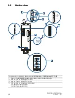
2
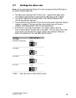
8-pin DIP switch
Meaning of the DIP switches:
–
S0
and
S1
with
function (Setting the data rate)
–
S0
and
S1
with
function (Setting the optical transmit power)
–
S2, S3, S4, S5, S8 without
function
3
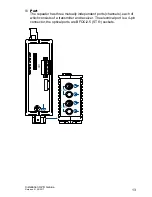
CH1 - electrical port
4
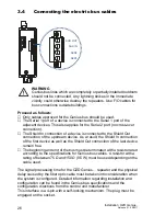
The information field for the electrical port 1 (CH1)
SHD OUT - Shield line, output (connected to casing)
SHD IN - Shield line, input (connected to casing via a capacitor)
SER2 = Data line S1
SER1 = Data line S2
5
CH2, CH3 - optical ports
6
Grounding screw
7
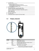
LED display element for system status and port status
Display
Color
Meaning
System
None
Supply voltage is too low
Green
Data reception at all ports
Red
No data reception for 500 ms at minimum one port
Ports
None
No data reception for 500 ms
Green
Data reception; no error detected
orange/yellow
Data reception, error detected:
–
echo error (fiber in sending direction interrupted)
–
malformed data packets (Jabber or Fragment)
CH3
System
CH1
CH2
CH1
Summary of Contents for OZD Genius G12
Page 40: ...40 Installation OZD Genius Release 01 09 2017...
Page 41: ...Installation OZD Genius Release 01 09 2017 41...
Page 42: ......

