8
Vision Board WR6BE User Manual
Introduction
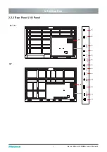
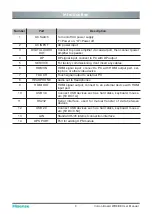
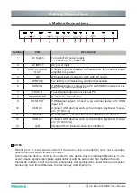
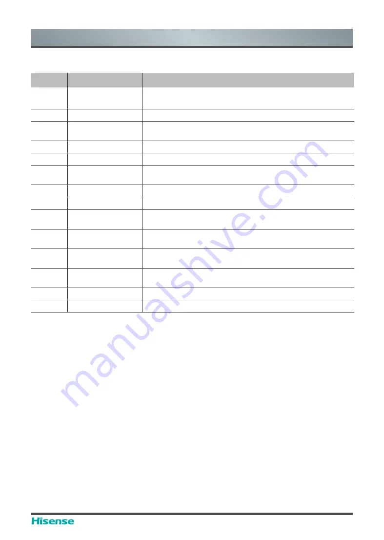
Number
Port
Description
1
AC Switch
Turn on/off AC power supply
“I”=Power on, “O”=Power off
2
AC INPUT
AC power input
3
DIGITAL AUDIO
OUT
Connect to power amplifier via coaxial port, then connect power
amplifier to speaker
4
DP
DP signal input, connect to PC with DP output
5
SERVICE
For factory commissioning, don’t insert any cables
6
HDMI IN
HDMI signal input, connect to PC with HDMI output port, set-
top box, or other video device
7
TOUCH
Touch signal output to external PC
8
HEADPHONE
Audio out to Headphones
9
HDMI OUT
HDMI signal output, connect to an external device with HDMI
input port
10
USB 3.0
Connect USB devices such as hard disks, keyboard, mouse,
etc. [5V DC/1A]
11
RS232
Serial interface, used for mutual transfer of data between
devices
12
USB 2.0
Connect USB devices such as hard disks, keyboard, mouse,
etc. [5V DC/0.5A]
13
LAN
Standard RJ45 Internet connection interface
14
OPS PORT
Port for adding OPS module
Summary of Contents for 65WR6BE
Page 1: ...Bar code...
Page 20: ...17 Vision Board WR6BE User Manual Installation Guide...


