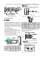
During installation, do not damage the insulation
material on the surface of the indoor unit.
3. The Installation of the Indoor Unit
Chart 3.1 Accessories
Insulation
(
small
)
Insulation
(
big
)
Clamp
Sealing material
Switch
tie
-
in
accessrory
Amount
1
1*
1
1
5
2
Used for liquid pipe
Used for gas pipe
Used for fixing
Used for insulation drainage
*
NOTE
:
only
the
18K
indoor
unit
contain
the
switch
tie
-
in
accessory
.
It
is
used
to
switch
9
.
52
gas
connection
tube
into
12
.
7
connection
tube
.
it
is
stalled
in
outdoor
unit
.
Parts
Usage
32
Installation and Maintenance
CAUTION
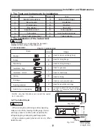
2. The Tools and Instruments for Installation
Number
1
2
3
4
5
6
7
Tool
Standard screwdriver
Vacuum pump
Charge hose
Pipe bender
Adjustable wrench
Tube cutter
Cross head screw-driver
Number
8
9
10
11
12
13
14
Tool
Knife or wire stripper
Gradienter
Hammer
Churn drill
Tube expander
Inner hexagon spanner
Tape measure
3.1 Accessories
3.2 The Initial Check
·
When moving the unit during or after unpacking,
make sure to lift it by holding its lifting lugs. DO not
exert any pressure on other parts, especially the
refrigerant piping, drain piping and flange parts.
·
Wear protective gears (gloves and so on). When
install the unit.
CAUTION
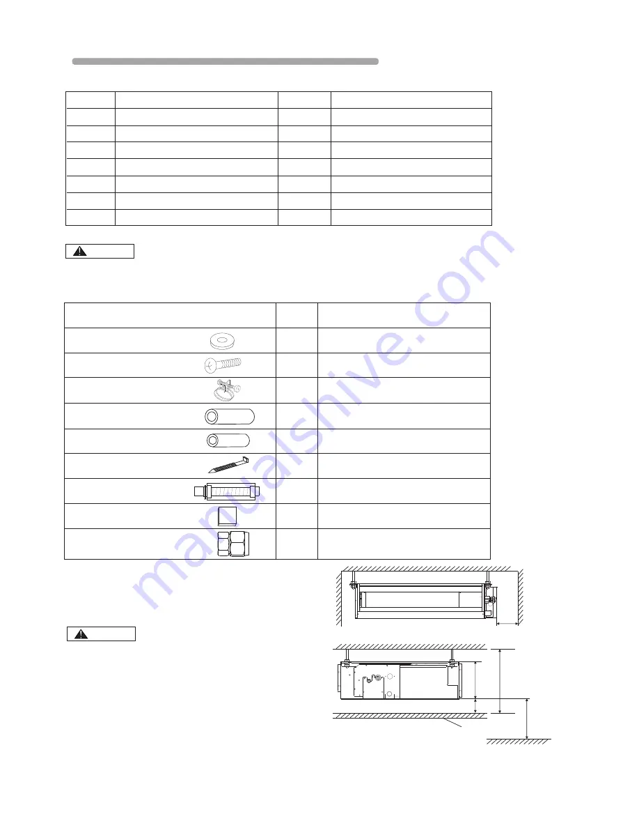
300
or more
Maintenance
space
Fig. 3.2.1
20 or more
190
Ceiling
230 or more
2500 or more
Floor surface
(Length: mm)
Fig. 3.2.2
Washer
Screw
Pipe fixing
Drainage
8
14
2
1
Used for indoor unit hang fixing
Used for fixing flange
Used for fixing drainage
Used for connect water pipe


