background image

9

9

.

.


P

P

A

A

R

R

T

T

S

S


L

L

I

I

S

S

T

T


 4

3

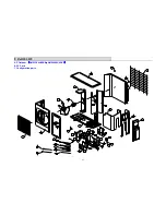
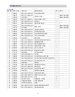
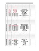
9-2-2. List 


KEY NO.  PART CODE 

PART NO. 

DESCRIPTION 

Q'TY  NOTE 

1202500 

RZA-0-1321-003-XX-0

FAN GUARD ASSY 


1202383 RZA-2-1112-004-XX-0

AMW3-24U4SKB

1312026 K31470022 

FRONT PANEL 

AMW4-28U4SKB

3 1202381 

RZA-0-1112-005-XX-0

RIGHT PANEL ASSY 


4 1202703 

RZA-2-2303-001-XX-0

HANDLE 

2  

5 1202610 

RZA-2-2228-002-XX-0

DRAINAGE 

HOSE 

1  

1301625 RZA-0-2202-254-XX-0

AMW3-24U4SKB

1312062 K31120001 

BASE ASSY 

1 AMW4-28U4SKB

7 1206628 

RZA-2-2502-001-XX-0

PROPELLER 

FAN 

1  

8 1301883 

RZA-0-0000-057-XX-1

FAN MOTOR ASSY 


9 1202442 

RZA-0-2506-003-XX-1

FAN SUPPORTER ASSY 


10 1202474 

RZA-0-2309-012-XX-0

TOP COVER ASSY 


11 1336593 

K13270009 

REACTOR 

1  

12 1301174 

RZA-2-1151-005-XX-0

PARTITION 

SUPPORT 

PLATE 

1  

13 1202234 

RZA-2-2431-005-XX-0

RUBBER BLOCK 


14 1204976 

RZA-0-1111-001-XX-2

BACK GUARD ASSY 


15 1301634 

RZA-0-1115-001-XX-0

SIDE PANEL  ASSY 


16 8001840 

RZA-2-2369-137-XX-0

VALVE 

COVER 

1  

17 

8001549 

RZA-2-5307-148-XX-0

ELECTRICAL BOX   


18 1312755 

K364A0002 


FILTER 

BOARD 

1  

19 1305257 

RZA-0-5220-024-XX-0

FILTER 1 


20 1202889 

RZA-0-2239-023-XX-0

FAN MOTOR CAPACITOR 


21 1301886 

RZA-4-2239-087-XX-0

AL 

ELECTROANALYSIS CAPACITOR 


22 1202283 

RZA-2-5301-002-XX-0

CAPACITORY CLIP 


23 1314803 

K36470009 

DUMMY 

1  

24 1201264 

RZA-0-5331-004-XX-0

BRIDGE 

RECTIFIER 

1  

25 1300277 

RZA-2-4127-045-XX-0

RADIATOR 

1  

26 8001834 

RZA-2-5307-149-XX-0

ELECTRICAL 

BOX 

1  

27 1336598 

K36411439 

CONTROL 

BOARD 

1  

28 

8001822 

RZA-2-5307-147-XX-0

ELECTRICAL BOX   


29 

1301643 

RZA-0-2233-005-XX-0

MOUNT PLATE ASSY 


30 1206639 

RZA-2-9030-012-XX-0

CLIP 

5** 


31 1301881 

4-2379-123-03-0 

TERMINAL 


PANEL 

4*  

32 1200858 

FJABX5000000008 FUSE 

BRACKET 


33 1200860 

FSYRT120T3D0008  FUSE 


1  

34 1300249 

RZA-2-2476-175-XX-0

NOISE 

DEFENING 

COVER 

1  

35 1204958 

RZA-2-5303-054-XX-0

SENSOR 

MOUNT 


1  

Summary of Contents for AMS-09UR4SNZA2

Page 1: ...MULTI SPLIT TYPE AIR CONDITONER SERVICE MANUAL V 2 0 INDOOR UNIT AMS 09UR4SNZA2 AMS 12UR4SNZA2 INDOOR UNIT AMW2 20U4SKB AMW3 24U4SKB AMW4 28U4SKB Hisense Corporation...

Page 2: ...IAGRAM 9 4 1 Refrigerant flow diagram 9 4 2 Evacuation procedures 11 4 3 Evacuation direction 12 5 ELECTRICAL DATA 13 5 1 Electric wiring diagrams 13 5 2 Electric control 15 5 3 Sensor parameter 18 6...

Page 3: ...RA AN NG GE E 1 Temperature Indoor Air Intake Temp Outdoor Air Intake Temp Maximum 32 D B 23 W B 43 D B 26 W B COOLING Minimum 21 D B 15 W B 21 D B 15 W B Maximum 27 D B 18 W B 24 D B 18 W B HEATING...

Page 4: ...99 9 99 9 99 9 Electrical data Max current A 15 0 15 0 14 5 SEER HSPF Model JU1015D5 JU1015D5 SNB130FGYM Compressor Winding resistance at25 0 661 0 650 0 639 0 661 0 650 0 639 0 58 20 Model YDK70 6H...

Page 5: ...kW 40 40 40 40 Auxiliary heater A Power factor Electrical data Starting current A SEER HSPF Model Compressor Winding resistance at25 Model YYW16 4 532 YYW16 4 532 Indoor fan motor Winding resistance a...

Page 6: ...odel YDK70 6H 3 YDK55 6I 8 Rated power source 220V 50Hz 220V 50Hz Phases Poles 1 6 1 6 Rated load output W 65 47 Ambient temperature 5 43 5 43 2 2 3 COMPRESSOR PARAMETER ELECTRIC PERFORMANCE AMW3 24U4...

Page 7: ...NCE AMW3 24U4SKB AMW4 28U4SKB AMW2 20U4SNB Filter model RTNF250 25T068X 03LF RTNF250 25T068X 03LF Rated current A 20 20 Rated power source AC 220V 50Hz AC 220V 50Hz Filter frequency range 150K 30MHHz...

Page 8: ...3 3 O OU UT TL LI IN NE ES S A AN ND D D DI IM ME EN NS SI IO O 6 3 1 INDOOR MODEL AMS 09UR4SNZA2 AMS 12UR4SNZA2 23mm 631mm 94mm 190mm 250mm 750mm 50mm 50mm 50mm 65mm...

Page 9: ...3 3 O OU UT TL LI IN NE ES S A AN ND D D DI IM ME EN NS SI IO O 7 3 2 OUTDOOR MODEL AMW2 20U4SNB...

Page 10: ...3 3 O OU UT TL LI IN NE ES S A AN ND D D DI IM ME EN NS SI IO O 8 3 3 OUTDOOR MODEL AMW3 24U4SKB AMW4 28U4SKB...

Page 11: ...RI IG GE ER RA AN NT T F FL LO OW W D DI IA AG GR RA AM M 9 4 1 Refrigerant flow diagram MODEL AMW3 24U4SKB AMW4 28U4SKB Filter B A A C B D C D Remark The part is only for AMW4 28U4SKB COOLING CYCLE...

Page 12: ...4 4 R RE EF FR RI IG GE ER RA AN NT T F FL LO OW W D DI IA AG GR RA AM M 10 MODEL AMW2 20U4SNB EEV B EEV A 4 way valve Filter B A A B Filter...

Page 13: ...d keep the pressure for one or two minutes Make sure the pressure is no change if the pressure is changed to high there is some leakage for the pipe connection Remove gage manifold valve quickly from...

Page 14: ...multi system a b c d 60m 40m Height difference I D O D 15m 15m Height difference I D I D 7 5m 7 5m Do your best to reduce the pipe length Long pipe may cause capacity of the indoor unit incline Total...

Page 15: ...R FILTER BOARD P2 P1 CAPACITOR YLW 1 1 2 1 2 1 1 1 4 4 2 3 2 3 8 8 6 5 5 6 7 7 9 9 10 10 BLU 2 BRN 2 L2 ORG 3 3 1 2 1 2 8 8 9 9 4 4 CN501 WHT 5 5 3 2 3 2 1 1 6 7 6 7 6 6 CN301 WHT CN901 WHT CN702 RED...

Page 16: ...FM POWER PANEL TERMINAL BLU FUSE BRN CONNECTION BRN BLU PANEL C 1 L TERMINAL YLW GRN 2 N 4 SI CONNECTION YLW GRN PANEL B TERMINAL BLU BRN CONNECTION PANEL A TERMINAL YLW GRN BLU BRN YLW GRN BRN 3 AMW2...

Page 17: ...5 5 E EL LE EC CT TR RI IC CA AL L D DA AT TA A 15 5 2 Electric control 1 Control board for indoor unit AMS 09UR4SNZA2 AMS 12UR4SNZA2...

Page 18: ...5 5 E EL LE EC CT TR RI IC CA AL L D DA AT TA A 16 2 Control board for outdoor unit AMW3 24U4SKB AMW4 28U4SKB 1 FILTER BOARD 3 15 250 2 CONTROL BOARD...

Page 19: ...5 5 E EL LE EC CT TR RI IC CA AL L D DA AT TA A 17 3 Control board for outdoor unit AMW2 20U4SNB 1 FILTER BOARD 2 CONTROL BOARD...

Page 20: ...9 0 3651 19 13 50 20 79 2 4516 125 7D 106 3 059 4 3367 221 DD 5 241 1 0 3830 20 14 51 20 01 2 4994 127 7F 107 2 97 4 3535 222 DE 4 229 0 4016 20 14 52 19 26 2 5471 130 82 108 2 884 4 3699 223 DF 3 217...

Page 21: ...86 0 725 4 3318 221 DD 9 22 82 0 8539 44 2C 39 3 151 2 9932 153 99 87 0 7053 4 3476 222 DE 8 21 75 0 8885 45 2D 40 3 041 3 0358 155 9B 88 0 6861 4 3631 223 DF 7 20 74 0 9237 47 2F 41 2 936 3 0775 157...

Page 22: ...e value is current temperature of outdoor The range of the value is from 19 to 45 will displayed when communication of indoor unit and outdoor unit abnormal 3 Frequency stand for the speed of compress...

Page 23: ...p it will automatically start and operate in the preset conditions 2 Timer off When set to stop in a set time by the remote controller the air conditioner will start in the timer off condition When th...

Page 24: ...et 3 it will be changed to the heating mode c When these conditions are not met it will remain in the previous run mode When the setting temperature is changed re judgment will be made for the run mod...

Page 25: ...1 6 in the cooling mode it swings between the positions 1 4 in the heating mode 3 9 Cold air prevention In the heating run to prevent the indoor fan from blowing cold air the indoor fan speed is cont...

Page 26: ...closed automatically 3 11 Mode interfere For the reason that all indoor units use one outdoor unit outdoor unit can only run with same mode cooling or heating so when the mode you set is different fr...

Page 27: ...from increasing the frequency If the temperature continues to rise the compressor will decrease the frequency If the indoor coil temperature is too high the compressor will stop working immediately Th...

Page 28: ...han shut down value and the system will reboot after three minutes Operation Shut down down freq Up limit Up limit Limit down shut down down up limit value value value release current start start rele...

Page 29: ...tioning mode is the operation mode set by users through remote controller five modes are available cooling heating dehumidification as welll as fan mode and automatic mode Automatic operation refers t...

Page 30: ...unit is vacancy and not any fault code will be reported z When communication fault to some indoor unit in operation procedure soft regard the indoor unit communicate faulted as turn off while other i...

Page 31: ...pe sensor on valve B fault 18 Gas pipe sensor on valve C fault 19 Gas pipe sensor on valve D fault 20 Current sensor fault 21 Voltage sensor fault 23 Emergency shutdown for discharge temperature abnor...

Page 32: ...nt control 3 Frequency forbid for coil temperature control of indoor unit A 4 Frequency forbid by coil temperature control of indoor unit B 5 Frequency forbid by coil temperature control of indoor uni...

Page 33: ...or sensor fault Top of the compressor sensor may be short circuited or disconnected 9 Outdoor coil temperature sensor fault Coil temperature sensor may be short circuited or disconnected 10 Defrosting...

Page 34: ...e sensor in indoor unit C is fault 28 Indoor unit D boot fault for freeze protection a Expand valve D is damaged leaking b The coil temperature sensor in indoor unit D is fault 30 Emergency shutdown f...

Page 35: ...ing The air condition should be installed in good ventilation Tool Pressure Gauge Technique see feel test SEE Tube defrost FEEL The difference between tube s temperature TEST Test pressure cooling run...

Page 36: ...ve and 4 way valve If the pressure is close to static pressure NO NO 4 way valve collude or compressor exhaust very ebb yes NO yes Heating mode Test system pressure Does the high pressure normal at se...

Page 37: ...imeter Insert screwdriver into to rotate indoor fan motor slowly for 1 revolution or over and measure voltage YELLOW and GND on motor The voltage repeat 0V DC and 5V DC Notes 1 Please don t hold motor...

Page 38: ...material Malfunction may not be observed at early stage after such shock But it may be found later this type of mishandling void our warranty 3 COMPRESSOR Coil Resistance JUS1015D5 at 25 0 66 U V 0 66...

Page 39: ...orce decreasing 4 INDUCTANCE Familiar error 1 Sound abnormality 2 Insulation resistance disqualification 5 STEP MOTOR 5 4 2 1 Test in resistance TOOL Multimeter Test the resistance of winding The step...

Page 40: ...3 2 Observe the deflection of the pointer setting the resistance measuring range of the multimeter to the maximum value The capacitor is good if the pointer bounces to a great extent and then gradual...

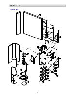
Page 41: ...9 9 P PA AR RT TS S L LI IS ST T 39 9 1 Indoor AMS 09UR4SNZA2 AMS 12UR4SNZA2 2 1 3 4 5 6 7 8 9 10 11 12 13 14 15 16 17 1 17 2 17 3 17 4 17 18 19 20 21 23 22 25 26 27 28 29 30 24...

Page 42: ...0 FAN MOTOR ASS Y 1 16 1203287 RZA 2 1523 056 XX 0 FLAP 1 17 1203747 RZA 0 2201 129 01 0 BASE ASS Y 1 17 1 1203271 RZA 2 2231 012 01 0 BASE 1 17 2 1203609 RZA 2 1519 037 01 0 BLADE 2 17 3 1203661 RZA...

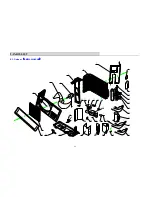
Page 43: ...76 29 27 28 30 25 26 23 24 22 21 20 18 17 16 15 14 13 10 6 5 1 2 3 11 8 7 9 12 4 35 32 34 33 36 37 39 40 T dis 38 Green Blue Black Yellow Yellow 73 74 Red 75 White 31 9 2 Outdoor AMW3 24U4SKB AMW4 28U...

Page 44: ...9 9 P PA AR RT TS S L LI IS ST T 42 2 System parts 56 49 50 48 51 52 53 54 55 57 60 65 59 72 41 45 42 43 46 47 61 44 66 68 69 70 71 58...

Page 45: ...76 RZA 0 1111 001 XX 2 BACK GUARD ASSY 1 15 1301634 RZA 0 1115 001 XX 0 SIDE PANEL ASSY 1 16 8001840 RZA 2 2369 137 XX 0 VALVE COVER 1 17 8001549 RZA 2 5307 148 XX 0 ELECTRICAL BOX 1 18 1312755 K364A0...

Page 46: ...79 RZA 0 4206 985 XX 0 DISTUIBUTOR ASS Y 1 52 1300178 RZA 0 4206 977 XX 0 DISTUIBUTOR ASS Y 1 53 1300278 RZA 0 4115 414 XX 0 CONDENSER INLET ASS Y 1 54 1300184 RZA 2 4118 001 XX 0 CONDENSER OUTLET TUB...

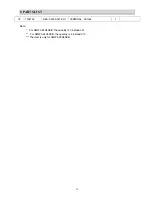
Page 47: ...AR RT TS S L LI IS ST T 45 76 1304193 RZA 0 5306 027 XX 1 TERMINAL PANEL 1 Note For AMW3 24U4SKB the quantity is 3 instead of 4 For AMW3 24U4SKB the quantity is 4 instead of 5 The item is only for AMW...

Page 48: ...9 9 P PA AR RT TS S L LI IS ST T 46 9 3 Outdoor AMW2 20U4SNB 2 3 4 5 6 36 7 26 27 21 20 8 13 15 37 24 1 19 35 34 32 31 30 29 28 9 14 17 10 11 12 16 22 23 33 25 38...

Page 49: ...01842 4 5259 290 01 0 TEMPERATURE SENSOR 1 18 1312582 K1C510001 TEMPERATURE SENSOR 1 19 1204958 RZA 2 5303 054 XX 0 SENSOR MOUNT ASSY 1 20 1304403 RZA 2 2476 195 XX 0 NOISE DEFENING COVER 1 1 21 12032...

Reviews: