background image

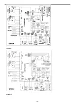
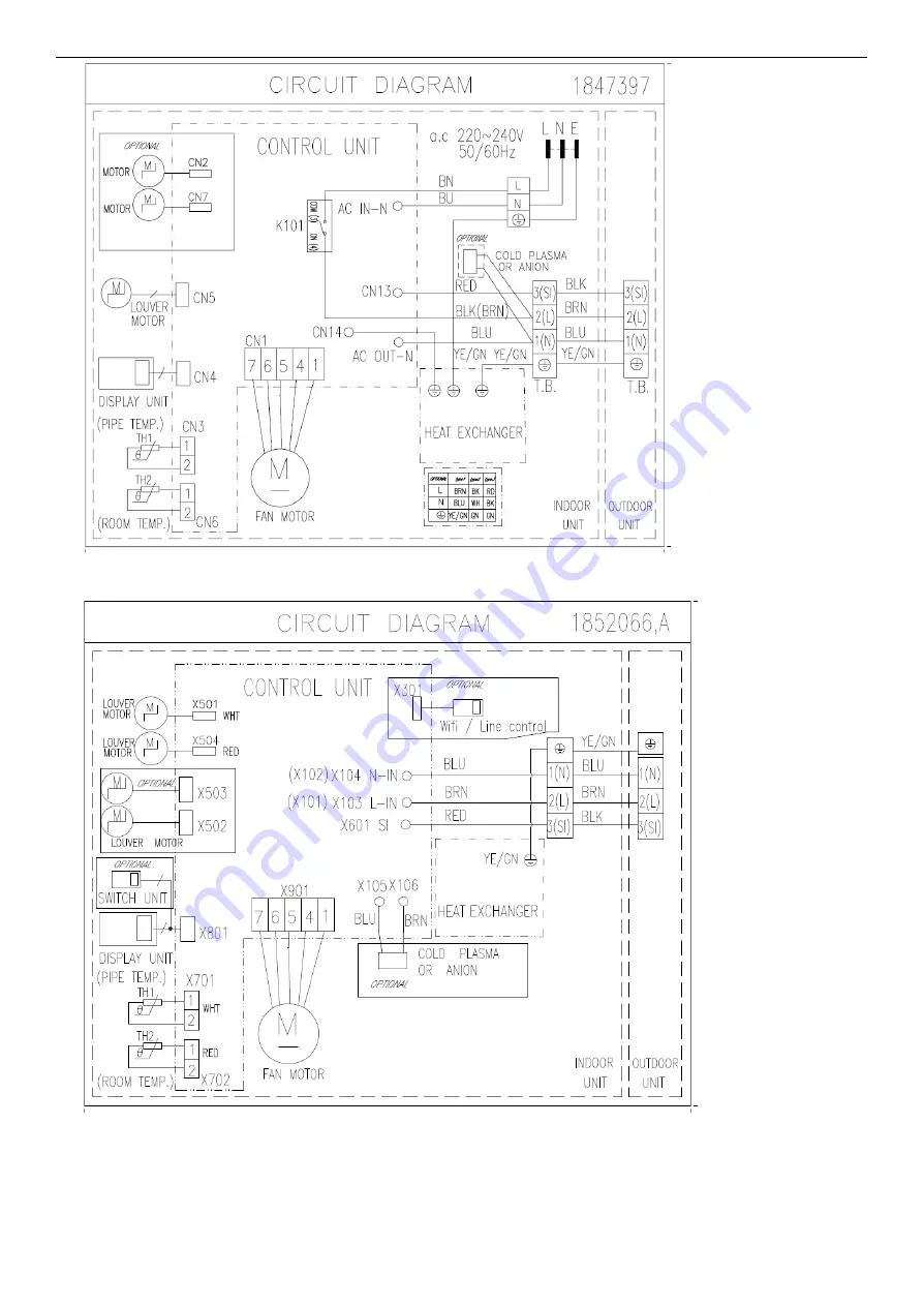
1852066

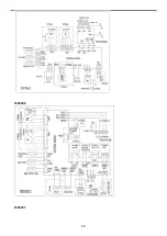
Outdoor:

1507746

23

Summary of Contents for AS-09TR2SYDDC01

Page 1: ...isense Corporation MODEL AS 09TR2SYDDX01 AS 12TR2SVEDX03 AS 18TR2SXADX01 AS 22TR2SBBDX01 AS 09UW4SVDTE09A AS 12UW4SVETE09A AS 18UW4SXATE AS 22UW4SBBTE AS 12UR4SVETG9 AS 22UW4SBBTG AS 09TR2SYDDC01 AS 1...

Page 2: ...ecifications 6 3 Product Picture and Drawing 12 3 1 Product Pictures 12 3 2 Product dimensions 16 4 Installation Instruction 18 4 1 Installation Place and Condition 18 4 2 Electric Wiring Diagram 20 4...

Page 3: ...s air conditioning system meets strict safety and operating standards As the installer or service person it is an important part of your job to install or service the system so it operates safely and...

Page 4: ...n cause dripping and water damage to walls and floors In Moist or Uneven Locations Use a raised concrete pad or concrete blocks to provide a solid level foundation for the outdoor unit This prevents w...

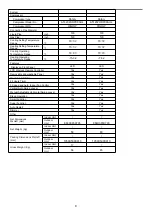
Page 5: ...2 3 21 3 5 Energy Class Cooling A A A Energy Class Heating B B A Refrigerant R410A R410A R410A Refrigerant charge volume 5M g 610 930 1340 Additional ref Volume g 20 20 20 Indoor Unit Noise Level High...

Page 6: ...nction Yes Yes Yes Super Function Yes Yes Yes Auto Restart Yes Yes Yes Dimmer Yes Yes Yes Other Net Dimensions WxHxD mm Indoor Unit Outdoor Unit 715 240 482 715 240 482 810 585 280 Net Weight Kg Indoo...

Page 7: ...K89D53UEZ1 ASN108D32UFZ ATM150D43UFZ Compressor MFG GMCC GMCC Connecting Pipe Diameter Liquid Pipe inch 1 4 1 4 1 4 Gas Pipe inch 3 8 3 8 1 2 Cooling Setting Temperature Range 16 30 16 30 16 30 Heatin...

Page 8: ...al L h 2 4 3 Air Circulation High m3 h 1150 1800 Mid m3 h Low m3 h EER for Cooling W W 3 25 3 58 COP for Heating W W 3 25 3 58 Energy Class Cooling A F Energy Class Heating A F Refrigerant R410A R410A...

Page 9: ...LED LCD Wireless Remote Controller Yes Yes Removable and washable Panel Yes Yes Washable PP Filter Yes Yes 24 Hours Timer Yes Yes 3 Speed and Auto Indoor Fan Control Yes Yes Vertical Auto Swing Louve...

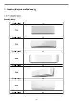
Page 10: ...3 Product Picture and Drawing 3 1 Product Pictures Indoor units Front Panel TD View Front Panel TE View Front Panel TG View Front Panel TQ View Front Panel DB View Front Panel DJ 10...

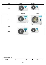
Page 11: ...View Front Panel TQ View Front Panel DC View Front Panel DN View Front Panel VT View Outdoor Units 11...

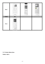
Page 12: ...Unit V W1M X W1T View Unit F W2M D W5F View Unit B W2T Y W1R View Remote controller Model L1 R1 J1 12...

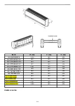
Page 13: ...View Model R2 View 3 2 Product dimensions Indoor units 13...

Page 14: ...870 270 215 AS 18TR2SXADC01 977 315 236 AS 22TR2SBBDC01 1149 315 236 AS 09UR4SVDTD9 780 270 208 AS 12UR4SVETD9 850 270 208 AS 18UR4SXATD 960 315 230 AS 09UW4SVDDN9 AS 12UW4SVEDN9 815 270 207 AS 18UW4...

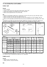
Page 15: ...AS 30UR4SDK 00 662 390 959 884 365 5 793 414 Note mean code of Front Panel 4 Installation Instruction To prevent abnormal heat generation and the possibility of fire do not place obstacles enclosures...

Page 16: ...unit within the maximum elevation difference H above or below the outdoor unit and within a total tubing length L from the outdoor unit as detailed See table 1 and c a b c table 1 Capacity Btu h Pipe...

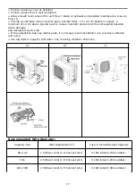
Page 17: ...it against possible water damage and decreased service life If the installation bag has rubber pads it is strongly recommended for use to reduce vibration and noise Use lug bolts or equal to bolt down...

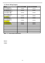
Page 18: ...67560 1877957 AS 12TE2SVE 03 AS 18TR2SXA 01 AS 22TR2SBB 01 1867560 1826526 AS 22TR2SBB 01 AS 18UR4SXA AS 18UW4SXA 1802900 1826526 AS 22UW4SBB 1861005 1826526 AS 09UR4SVD 9 AS 12UR4SVE 9 AS 09UW4SVD 9...

Page 19: ...1802900 1902289 19...

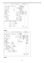
Page 20: ...1854605 1861005 20...

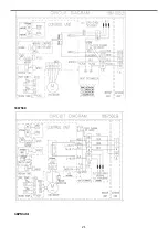
Page 21: ...1867560 1875124 21...

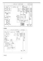
Page 22: ...1874568 1847397 22...

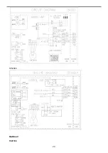
Page 23: ...1852066 Outdoor 1507746 23...

Page 24: ...1826526 1854707 24...

Page 25: ...1877957 1852132 25...

Page 26: ...1854446 4 3 Refrigerant Flow System 26...

Page 27: ...tightly shut 2 Connect joint of charging hose to vacuum pump 3 Fully open the handle of Lo manifold valve 4 Open the vacuum pump to evacuate At the beginning slightly loosen joint nut of low pressure...

Page 28: ...ce port to obtain the initial status 11 Retighten the cap 12 Leak test 4 5 Test Running Check after Installation Items to be checked Possible malfunction Has it been fixed firmly The unit may drop sha...

Page 29: ...ff valves of the connection pipes should be opened 4 All the impurities such as scraps and thrums must be cleared from the unit 2 Operation Test Method 1 Switch on power and press ON OFF button on the...

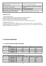
Page 30: ...take Temp Outdoor Air Intake Temp COOLING Maximum 30 46 Minimum 16 10 HEATING Maximum 30 24 Minimum 10 Note The parameters for generic only the exact value please refer to the product specification 5...

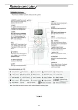
Page 31: ...J1 06 31...

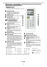
Page 32: ...R1 01 32...

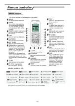
Page 33: ...33...

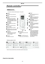
Page 34: ...R2 01 Function Instruction 34...

Page 35: ...irst time it would operate in the auto mode It will keep in stand by state if you press the ON OFF button during the normal operation When the appliance under the Stand by state press and hold the eme...

Page 36: ...eeds 26 b When the room temperature exceeds 23 but below 26 it will be ran in the Dry mode It will turn in Automatic setting After 3 min LOW air volume running c When the room temperature exceeds 21 b...

Page 37: ...y When the heating is changed to the cooling it needs an interval of 50 seconds for the 4 way valve to change over from being activated to being interrupted 3 7 Heating run mode 3 7 1 Temperature comp...

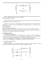
Page 38: ...and the operation diagram is shown as following When the difference between the setting temperature and the room temperature equal to 2 or 4 the indoor fan speed will keep in current speed 3 7 3 Air f...

Page 39: ...e the compressor and outdoor fan stop the indoor fan operate under the pre setting of air volume and the louver swing and the indoor fan speed same as the Heating Mode 5 3 Special Function Instruction...

Page 40: ...ng value in the current operating mode C If the temperature of coiled pipe is equal to or lower than minus two degrees centigrade EEPROM setting value in the current operating mode If the above three...

Page 41: ...1841765 AS 09TR2SYD 01 AS 12TE2SVE 03 AS 09TR2SYD 01 AS 12TR2SVE 03 AS 09UR4SVD 9 1550982 AS 18TR2SXA 01 AS 18TR2SXA 01 1550982 1952498 AS 22TR2SBB 01 AS 22TR2SBB 01 1564090 1841765 AS 09UW4SVD 09A AS...

Page 42: ...k from PG motor 6 Up down swing 7 Left right swing 8 Wiring control or wifi interface 9 Display interface 1 0 Protective tube 1841766 1898224 1 Interface of PG motor 2 Room temperature sensor 3 Pipe t...

Page 43: ...1550982 1 Interface of PG motor 2 Room temperature sensor 3 Pipe temperature sensor 4 Switch button 5 Feedback from PG motor 6 Up down swing 7 Left right swing 8 Display interface 9 Protective tube 43...

Page 44: ...1549681 1 Interface of PG motor 2 Room temperature sensor 3 Pipe temperature sensor 4 Switch button 6 Up down swing 7 Left right swing 8 Display interface 9 Protective tube 1564090 44...

Page 45: ...1916682 45...

Page 46: ...perature sensor 3 Pipe temperature sensor 4 Switch button 6 Up down swing 7 Left right swing 8 Display interface 9 Protective tube 1836919 1 Interface of PG motor 2 Room and Pipe temperature sensor 4...

Page 47: ...Model of outdoor 1555069 1887379 47...

Page 48: ...1841765 48...

Page 49: ...live wire connect to the terminal panel 2 L 1 0 Terminal of electronic expansion valve 1 4 Terminal of compressor overload protector 3 Terminal of reactor 7 cool valve terminal 1 1 Outdoor ambient te...

Page 50: ...1952498 50...

Page 51: ...mperature sensor YELLOW 17 DRED Function 3 Terminal of neutral wire connect to the terminal panel 1 N BLUE 8 Heater terminal RED 13 Outdoor pipe temperature sensor BLACK 18 4 Terminal of live wire con...

Page 52: ...ve 10 Terminal of live wire with filter board 1 5 Terminal of compressor V phase 3 Outdoor pipe temperature sensor 7 4 way valve terminal 11 Terminal of neutral wire with filter board 1 6 Terminal of...

Page 53: ...rminal of DC fan 8 Outdoor pipe temperature sensor 13 Cool Valve terminal 1 8 Terminal of neutral 4 Heat Sink temperature sensor 9 Terminal of compressor overload protector 14 Heater terminal 5 Pressu...

Page 54: ...lowly for 1 revolution or over and measure voltage YELLOW and GND on motor The voltage repeat 0V DC and 5V DC Notes 1 Please don t hold motor by lead wires 2 Please don t plug IN OUT the motor connect...

Page 55: ...894109636 15 30 196 0 72246147 36 3 58 2 937788018 14 28 755 0 75321223 37 3 455 2 980713033 13 27 392 0 78480857 38 3 335 3 023117961 12 26 103 0 81722911 39 3 219 3 065272268 11 24 882 0 85051031 4...

Page 56: ...44954 74 1 045 4 149715216 24 5 581 2 38741691 75 1 015 4 17007359 25 5 372 2 43506494 76 0 986 4 189944134 26 5 172 2 48247664 77 0 957 4 210004953 27 4 981 2 52951096 78 0 93 4 228855721 28 4 797 2...

Page 57: ...2 692216328 16 86 366 0 36494000 87 5 648 2 731362468 17 82 512 0 38068793 88 5 474 2 770083102 18 78 854 0 39694585 89 5 306 2 808524698 19 75 381 0 41372093 90 5 144 2 846617549 20 72 082 0 43102355...

Page 58: ...the winding The compressor is fault if the resistance of winding 0 short circuit or open circuit Familiar trouble 1 Compressor motor lock 2 Discharge pressure value approaches static pressure value 3...

Page 59: ...rd control a kind of control mode to control the machine startup shutdown based on the on off state of the room card control port 2 Fire protection a kind of control mode to control the machine startu...

Page 60: ...be 22AWG or above specification The switch is closed under normal conditions and off under abnormal conditions 3 When using the ON OFF function the user cuts off the short wire shown in Figure 2 and...

Page 61: ...s button or button Result On display screen the EE address increases or decreases by 1 0 255 correspondingly and the parameter data changes correspondingly 5 Operations In a state of that the symbol d...

Page 62: ...ne 3 pins of the OUT INPUT CN16 socket shown in the electrical wiring diagram of Figure 1 are tacitly approved to be in short circuit state under the factory state an external short circuit plug shown...

Page 63: ...of fire protection after the short circuit of fire protection signal release power on restrictions the wire controller maintains power off and the startup shutdown control is effective 3 ON OFF functi...

Page 64: ...ery second for the following faults Normal Outdoor coil temperature sensor in trouble a the outdoor coil sensor connect loose b the outdoor coil temperature sensor is failure c the outdoor control boa...

Page 65: ...exhaust temperature sensor is failure b the refrigerant of the unit is not enough Outdoor ambient temperature sensor in trouble a the outdoor ambient temperature sensor connect loose b the outdoor am...

Page 66: ...n cold weather Chip in outdoor board in trouble O a Using the wrong drive board b Using the wrong compressor AC voltage higher or lower protection O a the supply voltage is higher or lower than normal...

Page 67: ...will show the error code automatically when the unit has the following trouble Error code Power Timer Running Sleep Remark Light o Flash x OFF 1 2 3 4 Content Remark The root cause is may be one of t...

Page 68: ...denser is dirty f The outdoor unit has been installed without standard 6 AC voltage higher or lower protection a the supply voltage is higher or lower than normal b the inner supply voltage of the uni...

Page 69: ...Outdoor ambient temperature sensor in trouble a the outdoor ambient temperature sensor connect loose b the outdoor ambient temperature sensor is failure c the outdoor control board is failure 15 Compr...

Page 70: ...diator sensor fails b Detection circuit of the sensor on the control panel fails 27 Protection against too high system pressure a The pressure switch fails b The pressure detection switch on the contr...

Page 71: ...Runnin g Remark Light Flash x OFF 1 2 3 Content Remar k The root cause is may be one of the following 0 Normal 1 The failure for temperature sensor of outdoor coil a The outdoor temperature sensor loo...

Page 72: ...board is short circuit b the drive board is short circuit c the other components is short circuit 10 x x Communicatio n trouble between outdoor unit and driver a the connection wires connect loose b...

Page 73: ...e outdoor fan c the fan motor is failure d the outdoor control board is failure 21 x x Outdoor coil anti overload protection with cooling a the refrigerant is too much b the outdoor fan motor is failu...

Page 74: ...ol board is failure 39 Indoor fan motor run abnormally a There are something block the indoor fan motor b The fan motor cord connect loose c The fan motor is failure d The indoor control board is fail...

Page 75: ...oltage value for five seconds over voltage under voltage protection tarts 2 Protection actions against AC input over voltage under voltage The system stops operation 3 Conditions for ending AC input o...

Page 76: ...for anti overload of outdoor coiled pipe Condition for anti overload prohibition of frequency of outdoor coiled pipe in the case of anti overload frequency decreasing of outdoor coiled pipe anti overl...

Page 77: ...ine whether the connecting cables and tether cables of indoor outdoor units are correctly wired If not change wiring order and test connection Step two to determine whether there is loose connection F...

Page 78: ...2 DC Fan test point 78...

Page 79: ...3 4 79...

Page 80: ...5 80...

Page 81: ...81...

Page 82: ...DC fan motor test point 82...

Page 83: ...AC voltage test point Sensor test point 6 83...

Page 84: ...test point Check the screw of IPM fastening test point Forward of IPM P U P V P W test 84...

Page 85: ...Reverse of IPM P U P V P W test Forward of IPM N U N V N W test Reverse of IPM N U N V N W test 85...

Page 86: ...test point The resistance of the compressor U W V W 7 SI and N test point 86...

Page 87: ...87...

Reviews: