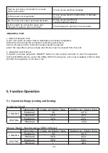
Has the unit been connected to a secure
earth connection?
It may cause electrical leakage.
Is the power cord specified?
It may cause electric malfunction or damage
the part.
Are the inlet and outlet openings blocked?
It may cause insufficient
cooling(heating)capacity.
Is the length of connection pipes and
refrigerant capacity been recorded?
The refrigerant capacity is not accurate.
△
Operation Test
1. Before Operation Test
(1)Do not switch on power before installation is finished completely.
(2)Electric wiring must be connected correctly and securely.
(3)Cut-off valves of the connection pipes should be opened.
(4)All the impurities such as scraps and thrums must be cleared from the unit.
2. Operation Test Method
(1)Switch on power and press “ON/OFF” button on the remote controller to start the operation.
(2)Press MODE button to select the COOL, HEAT (Cooling only unit is not available), FAN to check
whether the operation is normal or not.
5. Function Operation
5-1. Operation Range (cooling and heating
)
Argentina Model
:
Temperature
Indoor Air Intake Temp.
Outdoor Air Intake Temp
COOLING
Maximum
30
43
℃
Minimum
16
℃
16
℃
HEATING
Maximum
30
℃
24
℃
Minimum
/
-10
℃
Mexico Model ; North America SEER 16 Model
:
Temperature
Indoor Air Intake Temp.
Outdoor Air Intake Temp
COOLING
Maximum
30
46
℃
Minimum
16
℃
16
℃
HEATING
Maximum
30
℃
24
℃
Minimum
/
-10
℃
29
Summary of Contents for AS-09TR2SYDDC01
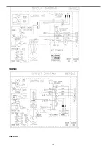
Page 13: ...View Model R2 View 3 2 Product dimensions Indoor units 13...
Page 19: ...1802900 1902289 19...
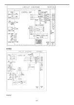
Page 20: ...1854605 1861005 20...
Page 21: ...1867560 1875124 21...
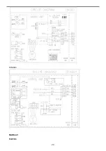
Page 22: ...1874568 1847397 22...
Page 23: ...1852066 Outdoor 1507746 23...
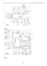
Page 24: ...1826526 1854707 24...
Page 25: ...1877957 1852132 25...
Page 26: ...1854446 4 3 Refrigerant Flow System 26...
Page 31: ...J1 06 31...
Page 32: ...R1 01 32...
Page 33: ...33...
Page 34: ...R2 01 Function Instruction 34...
Page 45: ...1916682 45...
Page 47: ...Model of outdoor 1555069 1887379 47...
Page 48: ...1841765 48...
Page 50: ...1952498 50...
Page 78: ...2 DC Fan test point 78...
Page 79: ...3 4 79...
Page 80: ...5 80...
Page 81: ...81...
Page 82: ...DC fan motor test point 82...
Page 83: ...AC voltage test point Sensor test point 6 83...
Page 84: ...test point Check the screw of IPM fastening test point Forward of IPM P U P V P W test 84...
Page 86: ...test point The resistance of the compressor U W V W 7 SI and N test point 86...
Page 87: ...87...


