1
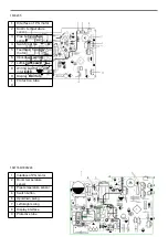
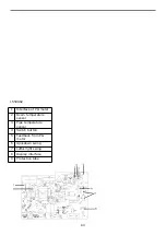
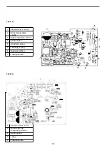
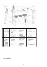
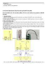
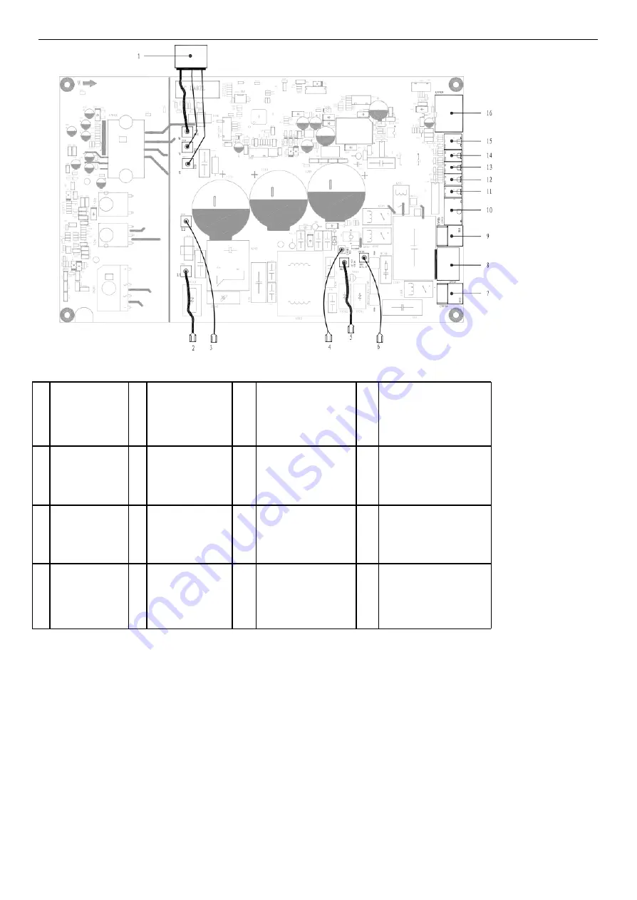
Terminal of
compressor
U/V/W phase
5
Terminal of
neutral wire,
connect to the
terminal panel
"1(N)"
9
4-way valve
terminal
1
3
Compressor
discharge
temperature sensor
2
Terminal of
reactor
6
Terminal of live
wire, connect
to the terminal
panel "2(L)"
1
0
Terminal of
electronic
expansion valve
1
4
Terminal of
compressor
overload
protector
3
Terminal of
reactor
7
cool valve
terminal
1
1
Outdoor ambient
temperature
sensor
1
5
Over pressure
sensor
4
Terminal of
signal wire,
connect to
the terminal
panel "3(SI)"
8
Terminal of AC
fan
1
2
Outdoor pipe
temperature
sensor
1
6
Terminal of DC fan
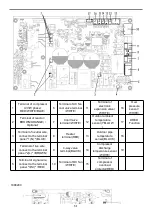
OU-PCB-SYD/SVE
49
Summary of Contents for AS-09TR2SYDDC01
Page 13: ...View Model R2 View 3 2 Product dimensions Indoor units 13...
Page 19: ...1802900 1902289 19...
Page 20: ...1854605 1861005 20...
Page 21: ...1867560 1875124 21...
Page 22: ...1874568 1847397 22...
Page 23: ...1852066 Outdoor 1507746 23...
Page 24: ...1826526 1854707 24...
Page 25: ...1877957 1852132 25...
Page 26: ...1854446 4 3 Refrigerant Flow System 26...
Page 31: ...J1 06 31...
Page 32: ...R1 01 32...
Page 33: ...33...
Page 34: ...R2 01 Function Instruction 34...
Page 45: ...1916682 45...
Page 47: ...Model of outdoor 1555069 1887379 47...
Page 48: ...1841765 48...
Page 50: ...1952498 50...
Page 78: ...2 DC Fan test point 78...
Page 79: ...3 4 79...
Page 80: ...5 80...
Page 81: ...81...
Page 82: ...DC fan motor test point 82...
Page 83: ...AC voltage test point Sensor test point 6 83...
Page 84: ...test point Check the screw of IPM fastening test point Forward of IPM P U P V P W test 84...
Page 86: ...test point The resistance of the compressor U W V W 7 SI and N test point 86...
Page 87: ...87...

