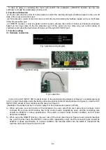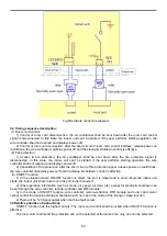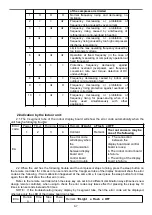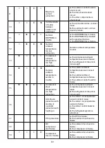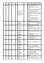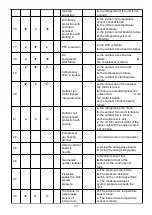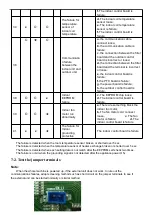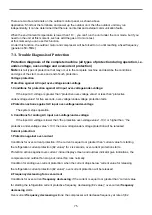
b.
the inner supply voltage of the
unit is higher or lower than normal
7
★
★
x
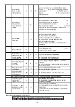
Communicatio
n failure
between the
indoor unit and
outdoor unit
a.
the communication cable
connect loose;
b.
the communication cable is
failure;
c.
the connection between the filter
board and the outdoor control
board is incorrect or loose;
d.
the connection between the filter
board and the terminal is incorrect
or loose;
e.
the indoor control board is
failure;
f.
the PFC board is failure;
g.
the power board is failure;
h.
the outdoor control board is
failure.
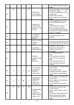
8
Current
overload
protection
a.
the fan motor run abnormally;
b.
the condenser and evaporator is
dirty;
c.
the air
inlet and outlet is abnormally
9
Maximum
current
protection
a.
the outdoor control board is
short circuit;
b.
the drive board is short circuit;
c.
the other components is short
circuit
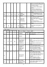
10
★
x
x
Communicatio
n trouble
between
outdoor unit
and driver
a.
the connection wires connect
loose
b.
the outdoor board or drive
board is failure;
11
Ο
x
x
Outdoor
EEPROM in
trouble
a.
the EEPROM chip is loose;
b.
the EEPROM chip inserted with
opposite direction;
c.
the EEPROM chip is failure
12
Outdoor
ambient
temperature
too low
protection
Outdoor ambient temperature too
low
13
Ο
x
★
Compressor
exhaust
temperature
too high
protection
a.
the compressor exhaust
temperature sensor is failure;
b.
the refrigerant of the unit is not
enough
14
★
★
Ο
Outdoor
ambient
temperature
sensor in
trouble
a.
the outdoor ambient temperature
sensor connect loose;
b.
the outdoor ambient
temperature sensor is failure;
c.
the outdoor control board is
failure
15
x
Ο
★
Compressor
shell
temperature
a.
the compressor exhaust
temperature sensor connect loose
72
Summary of Contents for AS-09TR2SYDDC01
Page 13: ...View Model R2 View 3 2 Product dimensions Indoor units 13...
Page 19: ...1802900 1902289 19...
Page 20: ...1854605 1861005 20...
Page 21: ...1867560 1875124 21...
Page 22: ...1874568 1847397 22...
Page 23: ...1852066 Outdoor 1507746 23...
Page 24: ...1826526 1854707 24...
Page 25: ...1877957 1852132 25...
Page 26: ...1854446 4 3 Refrigerant Flow System 26...
Page 31: ...J1 06 31...
Page 32: ...R1 01 32...
Page 33: ...33...
Page 34: ...R2 01 Function Instruction 34...
Page 45: ...1916682 45...
Page 47: ...Model of outdoor 1555069 1887379 47...
Page 48: ...1841765 48...
Page 50: ...1952498 50...
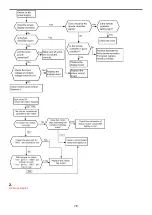
Page 78: ...2 DC Fan test point 78...
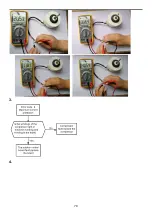
Page 79: ...3 4 79...
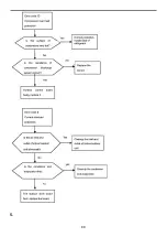
Page 80: ...5 80...
Page 81: ...81...
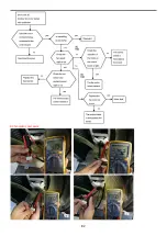
Page 82: ...DC fan motor test point 82...
Page 83: ...AC voltage test point Sensor test point 6 83...
Page 84: ...test point Check the screw of IPM fastening test point Forward of IPM P U P V P W test 84...
Page 86: ...test point The resistance of the compressor U W V W 7 SI and N test point 86...
Page 87: ...87...

