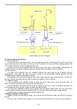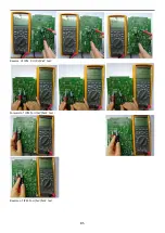
7-5. Trouble Diagnosis of Electric Filter Board
Visual examination: as the circuit is simple, the connection may be checked visually to see whether
any loose or poor connection.
Voltage test: the voltage at the input end shall be the same as the voltage at the output end.
7-6. Trouble Diagnosis of Electric Communication
Step one: to determine whether the connecting cables and tether cables of indoor/outdoor units are
correctly wired. If not, change wiring order and test connection.
Step two: to determine whether there is loose connection.
Fasten the connection in the case of loose connection and then conduct verification.
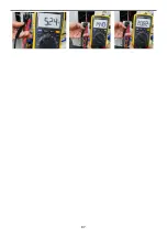
Step three: measure the voltage between SI and N with multi-meter and see whether the voltage
fluctuates between 0V and 24V. Please directly replace indoor and outdoor control boards if there are not
voltage fluctuations.
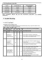
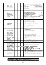
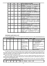
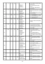
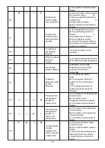
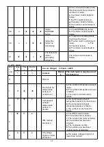
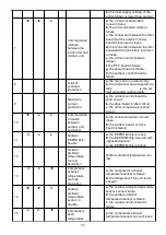
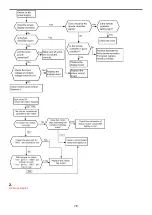
7.7.Diagnosis and Solution
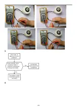
1.
77
Summary of Contents for AS-09TR2SYDDC01
Page 13: ...View Model R2 View 3 2 Product dimensions Indoor units 13...
Page 19: ...1802900 1902289 19...
Page 20: ...1854605 1861005 20...
Page 21: ...1867560 1875124 21...
Page 22: ...1874568 1847397 22...
Page 23: ...1852066 Outdoor 1507746 23...
Page 24: ...1826526 1854707 24...
Page 25: ...1877957 1852132 25...
Page 26: ...1854446 4 3 Refrigerant Flow System 26...
Page 31: ...J1 06 31...
Page 32: ...R1 01 32...
Page 33: ...33...
Page 34: ...R2 01 Function Instruction 34...
Page 45: ...1916682 45...
Page 47: ...Model of outdoor 1555069 1887379 47...
Page 48: ...1841765 48...
Page 50: ...1952498 50...
Page 78: ...2 DC Fan test point 78...
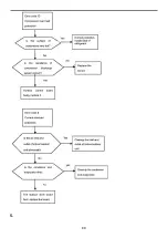
Page 79: ...3 4 79...
Page 80: ...5 80...
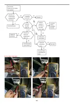
Page 81: ...81...
Page 82: ...DC fan motor test point 82...
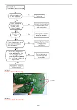
Page 83: ...AC voltage test point Sensor test point 6 83...
Page 84: ...test point Check the screw of IPM fastening test point Forward of IPM P U P V P W test 84...
Page 86: ...test point The resistance of the compressor U W V W 7 SI and N test point 86...
Page 87: ...87...

