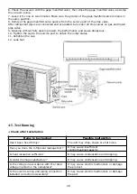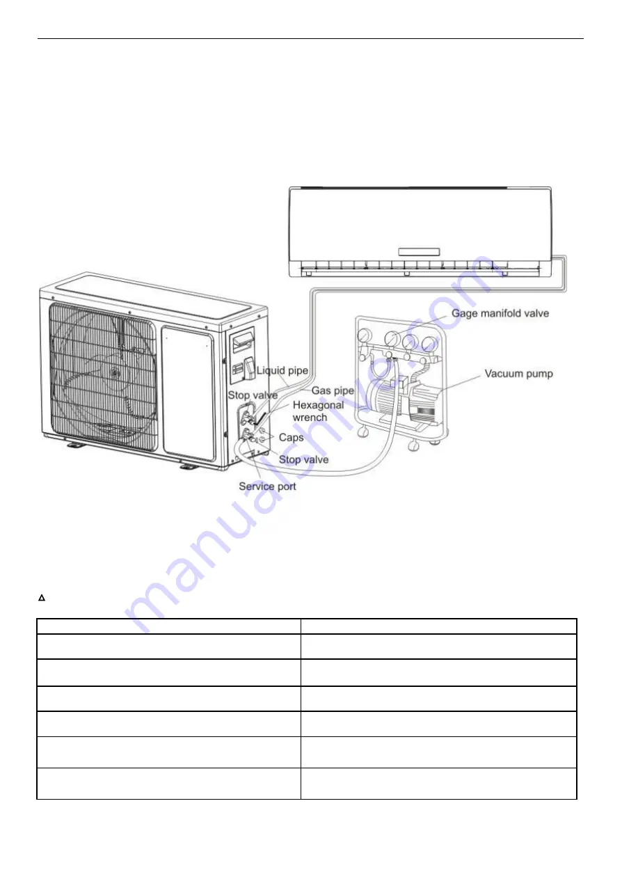
6. Check the vacuum with the gage manifold valve, then close the gage manifold valve, and stop
the vacuum pump.
7. Leave it for one or two minutes. Make sure the pointer of the gage manifold valve remains in
the same position.
8. Remove the gage manifold valve quickly from the service port of the stop valve.
After refrigerant pipes are connected and evacuated, fully open all stop valves on gas and liquid
pipe sides.
9. Opening without fully opening lowers the performance and cause dangerous.
10. Tighten the cap to the service port to obtain the initial status.
11. Retighten the cap
12. Leak test
4-5. Test Running
△
Check after Installation
Items to be checked
Possible malfunction
Has it been fixed firmly?
The unit may drop, shake or emit noise.
Have you done the refrigerant leakage test?
It may cause insufficient
cooling(heating)capacity
Is heat insulation sufficient?
It may cause condensation and dripping.
Is water drainage satisfactory?
It may cause condensation and dripping.
Is the voltage in accordance with the rated
voltage marked on the nameplate?
It may cause electric malfunction or damage
the product.
Is the electric wiring and piping connection
installed correctly and securely?
It may cause electric malfunction or damage
the part.
28
Summary of Contents for AS-09TR2SYDDC01
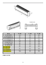
Page 13: ...View Model R2 View 3 2 Product dimensions Indoor units 13...
Page 19: ...1802900 1902289 19...
Page 20: ...1854605 1861005 20...
Page 21: ...1867560 1875124 21...
Page 22: ...1874568 1847397 22...
Page 23: ...1852066 Outdoor 1507746 23...
Page 24: ...1826526 1854707 24...
Page 25: ...1877957 1852132 25...
Page 26: ...1854446 4 3 Refrigerant Flow System 26...
Page 31: ...J1 06 31...
Page 32: ...R1 01 32...
Page 33: ...33...
Page 34: ...R2 01 Function Instruction 34...
Page 45: ...1916682 45...
Page 47: ...Model of outdoor 1555069 1887379 47...
Page 48: ...1841765 48...
Page 50: ...1952498 50...
Page 78: ...2 DC Fan test point 78...
Page 79: ...3 4 79...
Page 80: ...5 80...
Page 81: ...81...
Page 82: ...DC fan motor test point 82...
Page 83: ...AC voltage test point Sensor test point 6 83...
Page 84: ...test point Check the screw of IPM fastening test point Forward of IPM P U P V P W test 84...
Page 86: ...test point The resistance of the compressor U W V W 7 SI and N test point 86...
Page 87: ...87...

