background image


SERVICE MANUAL 

AS-09UR4SGN

PQ


Hisense Corporation 


第 1/51页

Summary of Contents for AS-09UR4SGNPQ

Page 1: ...SERVICE MANUAL AS 09UR4SGNPQ Hisense Corporation 第 1 51页 ...

Page 2: ...efrigerant flow diagram 4 2 Evacuation procedures 4 3 Evacuation direction 5 ELECTRICAL DATA 11 5 1 Electric wiring diagrams 5 2 Electric control 5 3 Sensor parameter 6 CONTROL MODE 16 6 1 control mode 18 7 TROUBLESHOOTING 26 7 1 Error codes 7 2 Service flow chart 8 CHECKING COMPONENTS 32 8 1 Check refrigerant system 8 2 Check parts unit 9 DISASSEMBLY INSTRUCTIONS 38 9 1 Indoor 9 2 Outdoor 10 PART...

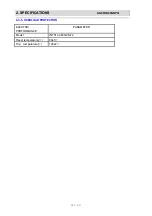
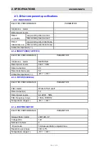
Page 3: ...P PE EC CI IF FI IC CA AT TI IO ON NS S A AS S 0 09 9U UR R4 4S SG GN NPQ 2 3 5 OVERLOAD PROTECTION ELECTRIC PERFORMANCE PARAMETER Model INT01L 4639 CS 74 Reset temperature 90 5 Trip temperature 120 4 第 3 51页 ...

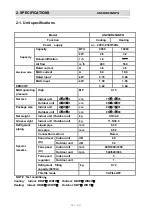
Page 4: ...a MAX input kW 1 50 1 85 EER COP 3 42 3 64 MAX operating pressure High MP 4 15 Indoor unit L W H cm 75 19 25 Net size Outdoor unit L W H cm 80 26 57 Indoor unit L W H cm 84 27 31 Package size Outdoor unit L W H cm 95 37 65 Net weight Indoor unit Outdoor unit kg 9 5 34 0 Gross weight Indoor unit Outdoor unit kg 11 5 38 5 Liquid pipe mm 6 35 Gas pipe mm 9 52 Refrigerant piping Connection method Flar...

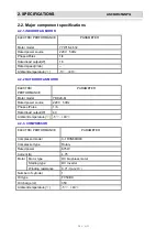
Page 5: ...utput W 16 Rated speed r min Ambient temperature 5 43 ELECTRIC PERFORMANCE PARAMETER Motor model YDK29 6I Rated power source 220V 50Hz Phases Poles 1 6 Rated load output W 40 Ambient temperature 5 43 ELECTRIC PERFORMANCE PARAMETER Compressor model C 1RVN68HOE Compressor type Rotary Rated power 675W Current A 4 75 Motor type DC brushless motor Starting type DC Inverter Motor Winding resistance 0 71...

Page 6: ...ance mH Filter winding rated inductance Ambient temperature ELECTRIC PERFORMANCE PARAMETER Inductance model R2050HSB Rated power source 220V 50Hz Rated current A 20 Rated inductance mH 5 2 Ambient temperature 20 70 ELECTRIC PERFORMANCE PARAMETER Filter model RTLB 12T047 02JF Rated current A 12 Rated power source AC 220V 50Hz Filter frequency range 150K 30MHHz Temperature range 25 85 ELECTRIC PERFO...

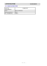
Page 7: ...P PE EC CI IF FI IC CA AT TI IO ON NS S A AS S 0 09 9U UR R4 4S SG GN NPQ 2 3 5 OVERLOAD PROTECTION ELECTRIC PERFORMANCE PARAMETER Model INT01L 4639 CS 74 Reset temperature 90 5 Trip temperature 120 4 第 7 51页 ...

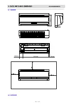
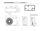
Page 8: ...3 3 O OU UT TL LI IN NE ES S A AN ND D D DI IM ME EN NS SI IO O A AS S 0 09 9U UR R4 4S SG GN NPQ 3 1 INDOOR 23mm 631mm 94mm 190mm 250mm 750mm 50mm 50mm 50mm 65mm 3 2 OUTDOOR 第 8 51页 ...

Page 9: ...3 3 O OU UT TL LI IN NE ES S A AN ND D D DI IM ME EN NS SI IO O A AS S 0 09 9U UR R4 4S SG GN NPQ 25cm 5cm 10cm Outlet 40cm 567 5 第 9 51页 ...

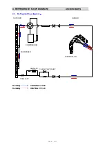
Page 10: ... T F FL LO OW W D DI IA AG GR RA AM M A AS S 0 09 9U UR R4 4S SG GN NPQ 4 1 Refrigerant flow diagram desiccator INDOOR OUTDOOR EVAPORATOR CONDENSER CAPILLARY CHECK VALVE ASS Y COMPRESSOR Remark COOLING CYCLE Remark HEATING CYCLE 第 10 51页 ...

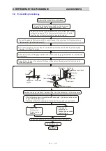
Page 11: ...tes 0 1 Mpa 76 cmHg Check the vacuum with the gage manifold valve then close the gage manifold valve and stop the vacuum pump Leave it as is for one or two minutes Make sure the pointer of the gage manifold valve remains in the same position Close Open Hexagonal wrench Stop valve pipe Connection Gage manifold valve Stop valve Liquid pipe Stop valve Hexagonal wrench Gas pipe Caps Service port Vacuu...

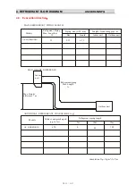
Page 12: ...th m A Piping size OD mm Length of connecting pipe m Gas Liquid Indoor unit Outdoor unit Models Indoor unit Outdoor unit MAX HEIGHT DIFFERENCE Outdoor unit precharged up to 7m Refrigerant piping length 15m 7m Max Height difference 7m Refrigerant piping Max Length A ADDITIONAL REFRIGERANT CHARGE R 410A g AS 09UR4SGNZA 15 9 52 6 35 670 45 0 Canculation Xg 15g m A 7 m 10m 120 AS 09UR4SGNZA 第 12 51页 ...

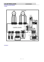
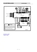
Page 13: ...5 5 E EL LE EC CT TR RI IC CA AL L D DA AT TA A A AS S 0 09 9U UR R4 4S SG GN NPQ 5 1 Electrical wiring diagrams 1 INDOOR 2 OUTDOOR 第 13 51页 ...

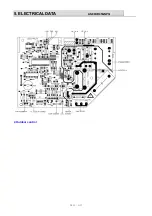
Page 14: ...5 5 E EL LE EC CT TR RI IC CA AL L D DA AT TA A A AS S 0 09 9U UR R4 4S SG GN NPQ 5 2 Electric control 1 Indoor control 第 14 51页 ...

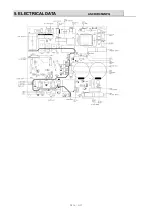
Page 15: ...5 5 E EL LE EC CT TR RI IC CA AL L D DA AT TA A A AS S 0 09 9U UR R4 4S SG GN NPQ 2 Outdoor control 第 15 51页 ...

Page 16: ...5 5 E EL LE EC CT TR RI IC CA AL L D DA AT TA A A AS S 0 09 9U UR R4 4S SG GN NPQ 第 16 51页 ...

Page 17: ...5 5 E EL LE EC CT TR RI IC CA AL L D DA AT TA A A AS S 0 09 9U UR R4 4S SG GN NPQ OUT IPM 第 17 51页 ...

Page 18: ...53 9 0 3651 19 13 50 20 79 2 4516 125 7D 106 3 059 4 3367 221 DD 5 241 1 0 3830 20 14 51 20 01 2 4994 127 7F 107 2 97 4 3535 222 DE 4 229 0 4016 20 14 52 19 26 2 5471 130 82 108 2 884 4 3699 223 DF 3 217 6 0 4209 21 15 53 18 54 2 5947 132 84 109 2 802 4 3856 224 E0 2 206 8 0 4409 22 16 54 17 85 2 6420 135 87 110 2 721 4 4012 224 E0 1 196 6 0 4617 24 17 55 17 19 2 6889 137 89 111 2 721 4 4012 224 E...

Page 19: ...504 150 96 86 0 725 4 3318 221 DD 9 22 82 0 8539 44 2C 39 3 151 2 9932 153 99 87 0 7053 4 3476 222 DE 8 21 75 0 8885 45 2D 40 3 041 3 0358 155 9B 88 0 6861 4 3631 223 DF 7 20 74 0 9237 47 2F 41 2 936 3 0775 157 9D 89 0 6676 4 3781 223 DF 6 19 79 0 9596 49 31 42 2 835 3 1188 159 9F 90 0 6496 4 3929 224 E0 5 18 88 0 9966 51 33 43 2 739 3 1590 161 A1 91 0 6323 4 4071 225 E1 4 18 02 1 0343 53 35 44 2 ...

Page 20: ......

Page 21: ...r machine communication function 3 3 Timer function 3 3 1 Timer on When set to start in a time by the remote controller the air conditioner starts in the timer on condition When the set time is up the air conditioner will turn on and operates in the preset conditions after receiving a signal from the remote controller If the air conditioner has not received a signal from the remote controller when...

Page 22: ...ine communication function after the unit is started the indoor fan operates at the ultra low flowrate for 20 seconds before selecting a run mode The room temperatures are detected during this period for the selection of a run mode In the first operation a When Troom Tset 3 it starts in the cooling mode b When 3 Troom Tset 3 it starts in the ventilation run mode c When Troom Tset 3 it starts in th...

Page 23: ...on is available only if the proper sensor is used and it is not available when it is subject to the sensor on the remote controller 3 7 2 Outdoor Fan The outdoor fan s speeds are divided into two levels which can be changed over according to outdoor ambient temperatures When operating at a fixed frequency the outdoor fan is forced to operate at the high speed 3 7 3 Indoor fan When the fan speed is...

Page 24: ...en set to open to one of the positions 1 6 as shown in the figure above it is fixed in the corresponding position 3 7 6 2 When the setting is automatic it swings between the positions 3 6 3 7 6 3 When set to sweep it swings between the positions 1 6 3 8 Heating run mode 3 8 1 Temperature compensation Principle for compensation The compensation is available only if the proper sensor is used and it ...

Page 25: ...res 3 8 6 4 way valve State It is electrified in heating Switchover When initially powered on for heating the 4 way valve is activated immediately In the change from cooling to heating it needs an interval of 50 seconds for the 4 way valve to change over from being interrupted to being activated 3 8 7 Flap control The flap opens to the position as shown in the figure below 3 8 7 1 During the cold ...

Page 26: ...sor stops 3 10 Air Blowing mode The outdoor unit does not work while the indoor fan runs with the fan speed selectable at the auto low medium and high speeds When being auto the fan speed is determined in the cooling mode with the temperature setting of 240 C in default The high medium and low fan speeds are same with that in the cooling mode 3 11 Compressor operating state indication When the com...

Page 27: ...tion at a fixed frequency 8 Communication frequency drops 3 12 Special notes 3 12 1 The outdoor unit of this model is electrified by the indoor unit control After the system starts to operate the indoor unit supplies the outdoor unit except for the ventilation mode If the EEPROM data is read correctly after turning on the power the indoor unit s beeper rings one time or if it is not the case the b...

Page 28: ...onding test circuit in trouble 6 Outdoor atmosphere temperature sensor short circuited open circuited or the corresponding test circuit in trouble 9 Ο Signal communication abnormal indoor outdoor 10 Ο Power module IPM protection 11 Ο Maximum current control 12 Ο Current overload control 13 Ο Compressor discharge temperature too high 14 Ο Over and under voltage control 18 Ο Compressor housing tempe...

Page 29: ...ble 8 Current overload control 36 Communication between the indoor and outdoor in trouble 9 Maximum current control 39 Indoor fan motor operation abnormal 10 4 way valve changeover abnormal 40 Grid protection alarm cabinet type 11 Outdoor EEPROM in trouble 41 Detecting failures by zero crossing 13 Compressor exhaust temperature too high control 14 Outdoor ambient temperature sensor in trouble 15 C...

Page 30: ...l board Display board trouble Indoor control board is faulty Replace it No Does it receive the remote controller signal Yes Start up self test function Is the remote controller in good condition Check the result Replace the battery press ACL button Retry remote operation After replacing the display board Display board problem Replace the indoor board Is there still trouble Yes Check operation Is i...

Page 31: ...r code 34 Indoor Coil sensor trouble Error code 33 Indoor temperature sensor Does the resistance of thermistor have the characteristics on part 6 3 Does the unit exit hot protector Replace the thermistor No Replace the indoor pcb board Take out from CN6 Measure the resistance of thermistor Take out from CN3 Meaure the resistance of thermistor Error code 14 Outdoor temperature sensor trouble Error ...

Page 32: ...controller Check the connector of indoor motor Does the socket CN1 1 3 of indoor control board have power input Indoor control board faulty and replace it Is resistance of main winding 0 short circuit or open circuit Replace the indoor fan motor Insert screwdriver into to rotate indoor fan motor slowly for 1 revolution or over and measure voltage CN2 1 3 Does voltage repeat DC 0V and DC 5V no yes ...

Page 33: ...re power output between 1 and 2 on terminal block of indoor unit Is there power output AC220V of indoor unit between N out and L out Indoor control board and replace it Is the system in good condition Outdoor IPM board trouble Indoor control board fault replace it Is the system in good condition Display board fault replace it Check operation Replace fuse Is unsafety voltage part of outdoor control...

Page 34: ...EM FLOW Conditions Compressor is running The air condition should be installed in good ventilation Tool Pressure Gauge Technique see feel test SEE Tube defrost FEEL The difference tube temperature TEST Test pressure cooling run heating run Lo Hi Outdoor unit Pressure gauge Lo Hi Outdoor unit Pressure gauge Test system flow 第 34 51页 ...

Page 35: ...valve and 4 way valve If the pressure is close to static pressure NO NO 4 way valve collude or compressor exhaust very ebb yes NO yes Heating mode Test system pressure Does the high pressure normal at service part The pressure on the high side The pressure on the low side Recharge refrigerant after air purging with the vacuum pump Does the high pressure normal over again Air remaining at the refri...

Page 36: ...otor connector while power ON 3 Please don t drop Hurl or dump motor against hard material Malfunction may not be observed at early stage after such shock But it may be found later This type of mishandling void our warranty 2 OUTDOOR FAN MOTOR Circuit diagram BROWN WHITE A2 M PINK WINDING M The main winding A The auxiliary winding Capacitor Hot protector 130 PURPLE YELLOW A1 A3 Winding resistance ...

Page 37: ... value 3 Compressor motor winding abnormality Notes 1 Don t put a compressor on its side or turn over 2 Please assembly the compressor in your air conditioner rapidly after removing the plugs Don t place the comp In air for along time 3 Avoiding compressor running in reverse caused by connecting electrical wire incorrectly 4 Warning In case AC voltage is impressed to compressor the compressor perf...

Page 38: ...circuit or open circuit 7 STEPPER MOTOR 5 4 2 1 Test in resistance TOOL Multimeter Test the resistance of winding The stepper motor is fault if the resistance of winding 0 short circuit or open circuit 8 2 3 Check others 1 FUSE Checking continuity of fuse on PCB ASS Y 1 Remove the PCB ASS Y from the electrical component box Then pull out the fuse from the PCB ASS Y Fig 1 Fuse PCB Ass抷 Fig 1 2 Chec...

Page 39: ...s as shown in Fig 3 Observe the deflection of the pointer setting the resistance measuring range of the multimeter to the maximum value The capacitor is good if the pointer bounces to a great extent and then gradually returns to its original position The range of deflection and deflection time differ according to the capacity of the capacitor Compressor motor capacitor Fan motor capacitor Multimet...

Page 40: ...installation plate 2 Remove the mounting plate Take out the mounting plate 3 Remove the front panel ASS Y 1 Hold the both sides of the front panel and drag it towards oneself and remove it 2 Take away the air filters in the grille 3 Take out the display panel and remove the display panel OPERATION PROCEDURE AND PHOTOS Screw Iinstallation plate Mounting plate Front plate Air filters Grille Display ...

Page 41: ... 1 Take out the screw of the electrical cover and remove it 2 Remove the indoor coil sensor from the sensor bracket 3 Take out the screws of the electrical control box and disconnect all the connectors on the printed circuit board Screws the electrical cover Room temperature sensor Display connector plug then remove the electrical box 5 Remove the evaporator 2 Take out the 6 screws of the evaporat...

Page 42: ...1 Take out the 2 screws of the cover and remove the cover of the bearing housing 2 Take out the 3 screws of the motor cover and remove the motor cover Take out the 1 special screw connecting the cross flow fan Screws Bearing housing Cover Screws Cover 3 Remove tthe fan motor and the cross flow fan Special screw Fan motor Cross flow fan 7 Remove the base ASS Y Drain hose ASS Y Base ASS Y 第 42 51页 ...

Page 43: ... 1 Take out the screws of the top panel and remove the top panel 6 Top panel Screws 2 Remove the front panel 1 Take out the 9 screws of the front panel and remove the panel Screws Front panel 3 Remove the side panel 1 Take out the 1 screw of the valve cover and remove the valve cover 2 Take out the 1 screw of the side cover and remove the cover Screws Valve cover Side cover Screws 第 43 51页 ...

Page 44: ...8 screws of the side panel 4 Remove the side panel Screws Side panel 4 Remove the electrical control box 1 Take out the 1 screw of the electrical box cover and remove it Screw Electrical box cover Electrical box 2 Disconnect all the wires and plugs in the electrical control box and the other parts filter Back guard 第 44 51页 ...

Page 45: ...ove the fan 2 Take out the 4 screws of the fan motor and remove the fan motor 3 Take out the 2 screws of the fan supporter and remove the fan supporter Special nut Screws 6 Remove the partition plate 2 Take out the 3 screws of the partition plate and remove the partition plate 1 Take out the 2 screws of the inductance take out the 1 screw of capacitor take out the 1 screw of capacitor Screw Partit...

Page 46: ...tition Cover Screws Partition 8 Check up the other parts of the outdoor units 1 Check up the condenser ass y 2 Check up the compressor ass y 3 Check up the base ass y 4 Check up the 4 way valve capillary tube and check valve 7 Remove the inductance at the base 5 Take out the screws of cover 4 Remove the inductance Inductance Screws 4 way valve Check valve Base Condenser Compressor Base 第 46 51页 ...

Page 47: ... 7 8 9 10 11 12 13 14 15 16 17 1 17 2 17 3 17 4 17 18 19 20 21 23 22 25 26 27 28 29 30 31 24 32 2 LIST Key No Part No Code name Description Q ty 1 K31470321 1393633 Front Panel 1 2 K31470201 8007483 Front Panel 1 3 RZA 0 2307 006 01 0 1203049 Air Filter Ass y 2 4 5 RZA 2 1501 076 XX 0 001265 grill Ass y 1 ...

Page 48: ...1 RZA 0 2231 019 XX 0 1203273 Base 1 17 2 RZA 2 1519 037 XX 0 1203280 Blade 2 17 3 RZA 2 2478 112 XX 0 1203661 flap fixed plate 2 17 4 RZA 2 2360 004 XX 0 1203627 Inner Flap 1 18 K33930002 1334532 Drainage Hose Ass y 1 19 RZA 0 0000 101 XX 0 1200853 Stepper Motor 1 20 K36430243 1377127 display ass y 1 21 RZA 2 2348 005 XX 0 1203590 Drainage Plug 1 22 RZA 2 2514 112 XX 0 1204031 Rubber Ring 1 23 RZ...

Page 49: ...1 10 0 P PA AR RT TS S L LI IS ST T A AS S 0 09 9U UR R4 4S SG GN NP PQ Q 10 2 Outdoor 1 Parts 39 13 40 38 37 36 35 34 33 32 31 30 29 28 27 26 25 24 23 22 20 19 18 17 16 15 14 12 9 7 6 5 4 3 2 1 11 ...

Page 50: ...04869 RZA 0 4515 02B 41 0 1 16 3 8 VALVE ASSY 1204871 RZA 0 4518 01B 41 0 1 17 SENSOR MOUNT ASSY 1204958 RZA 2 5303 054 XX 0 1 18 AMBIENT TEMPERATURE SENSOR 1205018 4 5259 395 01 0 1 19 COIL TEMPERATURE SENSOR 1201221 RZA 0 5259 106 XX 0 1 20 DISCHARGE TENPERATURE SENSOR 1201219 RZA 0 5259 090 XX 0 1 21 22 ELECTRICAL BOX COVER ASSY 1204048 RZA 0 5302 011 XX 1 1 23 CONTROL BOARD ASSY 1338175 K36411...

Page 51: ...IS ST T A AS S 0 09 9U UR R4 4S SG GN NP PQ Q 37 NOISE DEFENING COVER 4 1304957 RZA 2 2476 200 XX 0 1 38 COMPRESSOR ASSY 1319474 K37210044 1 39 DRAINAGE HOSE 1204014 852 2 2228 132 02 0 1 40 BASE ASSY 1203756 RZA 0 2202 179 XX 0 1 ...

Reviews: