5
5
.
.
C
C
O
O
N
N
T
T
R
R
O
O
L
L
M
M
O
O
D
D
E
E
L
L
18
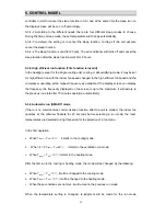
5-1. Major general technical parameters
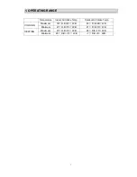
5-1-1 Conditionings for operation: Ambient temperatures: (-15 - +45
℃
), relative humidity (45 -
85%).
5-1-2 Remote receiver distance: 8 m.
5-1-3 Remote receiver angle: Less than 80 degrees.
5-1-4 Temperature control accuracy: ±1
℃
.
5-1-5 Time error: Less than 1%.
5-1-6 The power supply for the air conditioner is a.c 220V, 50Hz, with its fluctuation in the
range of (198
~
264V).
5-2. Functions of the controller
5-2-1 Display panel
I. Control functions of the remote controller (See operating and installation manual)
II. Display of the indoor unit Information on the screen:
Displaying Scheme:
Temperature display
:
Display set temperature or indoor temperature , and display fault code in
trouble indicating. An error code is displayed according to the signal from the indoor CPU. The
error code will flash for 5 seconds while displayed.
Running indicator
:
It is on during operation. It flashes in 10s after the sleep modehas been
setted.
TIMER indicator
:
When the timer mode works, the indicator will be lighted.
Sleep indicator
:
When the sleep mode works, the indicator will be lighted.
Compressor indicator
:
It lights up when compressor is running.
Remote control receiver
:
This section receives signals from the remote controller.
5-3. Control function
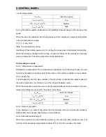
5-3-1 Emergency switch
5-3-1-1 Press the emergency switch once to turn on the machine and press it again to turn off
the machine; in the automatic mode, the indoor control temperature is set at 24
℃
with the
indoor fan speed setting is automatic and the flaps sweep.
5-3-1-2 When the machine is turned on (in the OFF condition), press and hold the emergency
switch for 5 seconds, the buzzer rings for 3 times and the controller starts in the trial operation.
The trial operation is the forced cooling with the indoor fan speed being set at high speeds,
the flaps sweeping and the air conditioner’s operation is irrelevant with room temperatures.
Summary of Contents for AS-09UR4SVNVG1 (UP1)
Page 1: ...AS 09UR4SVNVG1 UP1 AS 12UR4SVNVG1 UP1...
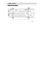
Page 8: ...3 3 I IN NS ST TA AL LL LA AT TI IO ON N 7 5 Outdoor unit feet distance...
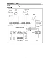
Page 9: ...4 4 E EL LE EC CT TR RI IC CA AL L D DA AT TA A 7 4 1 Electrical wiring diagrams 4 1 1 INDOOR...
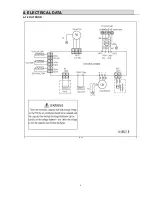
Page 10: ...4 4 E EL LE EC CT TR RI IC CA AL L D DA AT TA A 8 4 1 2 OUTDOOR...


