5
5
.
.
C
C
O
O
N
N
T
T
R
R
O
O
L
L
M
M
O
O
D
D
E
E
L
L
24
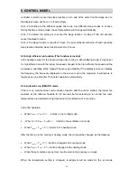
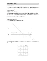
Dehumidifying area II: The compressor stops for 5 minutes and operators for 5 minutes at the
lowest frequency.
Dehumidifying area III: The compressor stops.
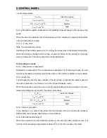
5-3-10 Air Blowing mode
The outdoor unit does not work while the indoor fan runs with the fan speed selectable at the
auto, low, medium and high speeds.
When being auto, the fan speed is determined in the cooling mode (with the temperature
setting of 24
0
C in default).
The high, medium and low fan speeds are same with that in the cooling mode.
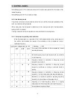
5-3-11 Compressor operating state indication
When the compressor is in operation, The 3 LED indicator lights on the control panel of
the outdoor unit indicates the causes of the restriction on the compressor’s current
operating frequency.
Symbols for indicator light::
★
: ON
Ο
: flashing
×
: OFF
LED1
LED2 LED3
The cause of the restriction on the compressor’s current
operating frequency
1
Ο
Ο
Ο
Normal frequency ascent and descent with no restriction
on the frequency
2
×
×
★
Frequency descent or restriction on frequency ascent
caused by over current
3
×
★
★
Frequency descent or restriction on frequency ascent
caused by anti-freeze in cooling or overload control in
heating
4
★
×
★
Frequency descent or restriction on frequency ascent
caused by too high compressor discharge temperature
5
×
★
×
Restriction on maximum operation operating frequency
caused by too low voltage on the supply circuit
6
★
★
★
Operating at a fixed frequency (when in a capacity
measurement or forced operation at a fixed frequency.)
8
★
×
×
Communication frequency drops.
Summary of Contents for AS-09UR4SVNVG1 (UP1)
Page 1: ...AS 09UR4SVNVG1 UP1 AS 12UR4SVNVG1 UP1...
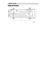
Page 8: ...3 3 I IN NS ST TA AL LL LA AT TI IO ON N 7 5 Outdoor unit feet distance...
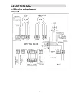
Page 9: ...4 4 E EL LE EC CT TR RI IC CA AL L D DA AT TA A 7 4 1 Electrical wiring diagrams 4 1 1 INDOOR...
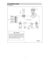
Page 10: ...4 4 E EL LE EC CT TR RI IC CA AL L D DA AT TA A 8 4 1 2 OUTDOOR...

