background image

7

7

.

.


C

C

H

H

E

E

C

C

K

K

I

I

N

N

G

G


C

C

O

O

M

M

P

P

O

O

N

N

E

E

N

N

T

T

S

S


36


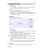
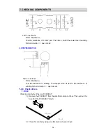
Test in resistance. 

TOOL: Multimeter. 

Test the resistance of “LOAD” port. The filter is fault if the resistance of winding 

0(short circuit)or

∞(

open circuit


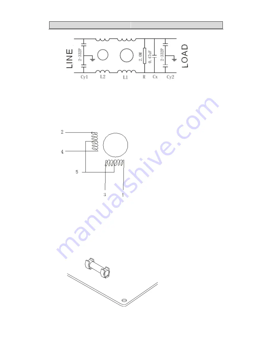
6. STEPPER MOTOR 


Test in resistance. 

TOOL: Multimeter. 

Test the resistance of winding. The stepper motor is fault if the resistance of 

winding 0(short circuit)or

∞(

open circuit

7-2-3. Check others   

      1. FUSE 


Checking continuity of fuse on PCB ASS’Y. 

1)  Remove the PCB ASS’Y from the electrical component box. Then pull out the 

fuse from the PCB ASS’Y (Fig.1) 

Fuse

PCB Ass抷

Fig.1


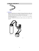
2)  Check for continuity using a multimeter as shown in Fig.2. 

Summary of Contents for AS-09UR4SVNVG1 (UP1)

Page 1: ...AS 09UR4SVNVG1 UP1 AS 12UR4SVNVG1 UP1...

Page 2: ...IFICATION 3 INSTALLATION 4 ELECTRICAL DATA 5 CONTROL MODE 6 TROUBLE SHOOTING 7 CHECKING COMPONENTS NOTE The figure size and parameter of the product may not be identical with the service manual please...

Page 3: ...RA AN NG GE E 1 Temperature Indoor Air Intake Temp Outdoor Air Intake Temp COOLING Maximum 32 D B 23 W B 43 D B 26 W B Minimum 21 D B 15 W B 21 D B 15 W B HEATING Maximum 27 D B 18 W B 24 D B 18 W B...

Page 4: ...oise Level High dB A 39 39 Low dB A 34 34 Outdoor Unit Noise Level dB A 52 52 Power Supply Voltage Frequency Phase V 220 240V 50Hz 1P 220 240V 50Hz 1P Rated Current Cooling A 3 8 4 5 Heating A 3 7 4 1...

Page 5: ...cking Dimensions WxHxD mm Indoor Unit 800 325 245 800 325 245 Outdoor Unit 830 530 315 830 530 315 Gross Weight Kg Indoor Unit 9 9 Outdoor Unit 28 30 Loading Capacity 20 40 40 HC 148 298 350 148 298 3...

Page 6: ...Oil type Zegles RB68EP or equivalent Oil charge cc 370 10 Input power W 910 5 Current A 4 3 Ambient temperature 5 43 2 3 Other component specifications 2 3 1 LOUVER MOTOR ELECTRIC PERFORMANCE PARAMETE...

Page 7: ...y b we should protect famous ancient buildings during installation c the installation does not affect the traffic The distance between air outlet of outdoor unit and the opposite object should be more...

Page 8: ...3 3 I IN NS ST TA AL LL LA AT TI IO ON N 7 5 Outdoor unit feet distance...

Page 9: ...4 4 E EL LE EC CT TR RI IC CA AL L D DA AT TA A 7 4 1 Electrical wiring diagrams 4 1 1 INDOOR...

Page 10: ...4 4 E EL LE EC CT TR RI IC CA AL L D DA AT TA A 8 4 1 2 OUTDOOR...

Page 11: ...ds while displayed Running indicator It is on during operation It flashes in 10s after the sleep modehas been setted TIMER indicator When the timer mode works the indicator will be lighted Sleep indic...

Page 12: ...turning on nor turning off operation will cancel the operator machine communication function 5 3 2 3 In default the air conditioner is set to start the operator machine communication function 5 3 3 T...

Page 13: ...pressor operating at the highest frequency as available If the display screen can display the frequency the frequency displayed on the screen is up to the maximum It will restore to the previous run s...

Page 14: ...the auto run which is same as cooling and heating 5 3 7 Cooling run mode 5 3 7 1 Temperature compensation Principle for compensation The compensation is available only if the proper sensor is used an...

Page 15: ...ion is available only if the proper sensor is used and it is not available when it is subject to the sensor on the remote controller or line controller 5 3 8 2 Indoor fan The fan speed is set at the h...

Page 16: ...n initially powered on for heating the 4 way valve is activated immediately In the change from cooling to heating it needs an interval of 50 seconds for the 4 way valve to change over from being inter...

Page 17: ...of the outdoor unit indicates the causes of the restriction on the compressor s current operating frequency Symbols for indicator light ON flashing OFF LED1 LED2 LED3 The cause of the restriction on...

Page 18: ...ing two times and the system cannot be started Normally when the indoor unit receives a control signal from the remote controller and emergency button the system will be started and the beeper will ri...

Page 19: ...trouble 9 Signal communication abnormal indoor outdoor 10 Power module IPM protection 11 Maximum current control 12 Current overload control 13 Compressor discharge temperature too high 14 Over and u...

Page 20: ...tdoor in trouble 9 Maximum current control 39 Indoor fan motor operation abnormal 10 Communication trouble between outdoor unit and driver unit 40 Grid protection alarm cabinet type 11 Outdoor EEPROM...

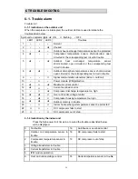
Page 21: ...lay board trouble Indoor control board is faulty Replace it No Does it receive the remote controller signal Yes Start up self test function Is the remote controller in good condition Check the result...

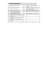
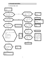
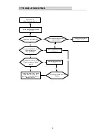
Page 22: ...door Coil sensor trouble Error code 33 Indoor temperature sensor Does the resistance of thermistor have the characteristics on part 6 3 Does the unit exit hot protector Replace the thermistor No Repla...

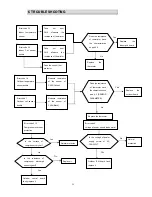
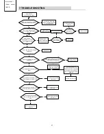
Page 23: ...eck the connector of indoor motor Does the socket CN1 1 3 of indoor control board have power input Indoor control board faulty and replace it Is resistance of main winding 0 short circuit or open circ...

Page 24: ...ard and replace it Is the system in good condition Outdoor IPM board trouble Indoor control board fault replace it Is the system in good condition Display board fault replace it Check operation Replac...

Page 25: ...itions Compressor is running The air condition should be installed in good ventilation Tool Pressure Gauge Technique see feel test SEE Tube defrost FEEL The difference tube temperature TEST Test press...

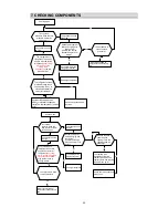
Page 26: ...way valve If the pressure is close to static pressure NO NO 4 way valve collude or compressor exhaust very ebb yes NO yes Heating mode Test system pressure Does the high pressure normal at service par...

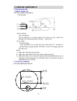
Page 27: ...ter Insert screwdriver into to rotate indoor fan motor slowly for 1 revolution or over and measure voltage BLACK and GND on motor The voltage repeat 0V DC and 5V DC Notes 1 Please don t hold motor by...

Page 28: ...TOOL Multimeter Test the resistance of the winding The compressor is fault if the resistance of winding 0 short circuit or open circuit Familiar trouble 1 Compressor motor lock 2 Discharge pressure va...

Page 29: ...EPPER MOTOR Test in resistance TOOL Multimeter Test the resistance of winding The stepper motor is fault if the resistance of winding 0 short circuit or open circuit 7 2 3 Check others 1 FUSE Checking...

Page 30: ...n Fig 3 Observe the deflection of the pointer setting the resistance measuring range of the multimeter to the maximum value The capacitor is good if the pointer bounces to a great extent and then grad...

Reviews: