background image

55


34 


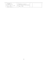
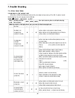
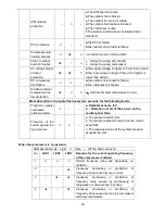
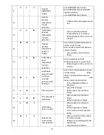
The failure for 

temperature 

sensor of 

indoor coil 

temperature   

a.

The indoor coil temperature

sensor loose;

b.

The indoor coil temperature

sensor is failure;

c.

The indoor control board is

failure.

36 


Communicatio

n failure 

between the 

indoor unit and 

outdoor unit 

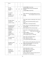
a.

the communication cable

connect loose; 

b.

the communication cable is

failure; 

c.

the connection between the filter

board and the outdoor control 

board is incorrect or loose; 

d.

the connection between the filter

board and the terminal is incorrect 

or loose;     

e.

the indoor control board is failure;

f.

the PFC board is failure; 

g.

the power board is failure;

h.

the outdoor control board is

failure. 

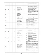
38 


Indoor 

EEPROM 

failure 

a.

The EEPROM chip loose;

b.

The indoor control board is

failure

39 


Indoor fan 

motor run 

abnormally 

a.

There are something block the

indoor fan motor;

b. The fan motor cord connect

loose; 

c. The fan motor is failure;

d. The indoor control board is

failure 

41 


The failure for 

Indoor 

grounding 

protective   

The indoor control board is failure 

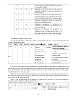
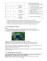
2.2    LED    display 

Error 

code 

Sleep  Timer  Running 

Remark

:★

Light 

 Flash 

x OFF


Content 

Remark 

The root cause is may be one of 

the following 

Normal 


The failure for 

temperature 

sensor of 

outdoor coil 

d.

The outdoor temperature sensor

loose;

e.

The outdoor temperature sensor

is failure;

f.

The indoor control board is failure

Summary of Contents for AS-10UR4SYDTDI

Page 1: ...1 Version 1 9 Hisense Corporation MODEL AS 10UR4SYDTDI AS 13UR4SYDTDI AS 18UR4SFATDI6 AS 24UR4SDBTDI6 EXPERT EU INVERTER...

Page 2: ...uctions are all you need for most installation sites and maintenance conditions If you require help for a special problem contact our sales service outlet or your certified dealer for additional instr...

Page 3: ...an drifting snow Provide snow vents When Connecting Refrigerant Tubing Use the flare method for connecting tubing Apply refrigerant lubricant to the matching surfaces of the flare and union tubes befo...

Page 4: ...500 Air Circulation CMH Max 550 EER for Cooling W W 3 21 5 6 COP for Heating W W 3 61 3 8 Refrigerant R410A Refrigerant charge volume g 620 Indoor Unit Noise Level High dB A 55 Low dB A 47 Outdoor Uni...

Page 5: ...Controller Yes Removable and washable Panel Yes Washable PP Filter Yes 24 Hours Timer Yes 3 Speed and Auto Indoor Fan Control Yes Vertical Auto Swing Louver Yes Manual Adjustable Horizontal Swing Louv...

Page 6: ...6 Gross Weight Kg Indoor Unit 9 5 Outdoor Unit 24...

Page 7: ...1 COP for Heating W W 3 51 3 8 Refrigerant Refrigerant charge volume g 850 Indoor Unit Noise Level High dB A 55 Low dB A 45 Outdoor Unit Noise Level dB A 62 Power Supply Voltage Frequency Phase 220 24...

Page 8: ...nel Yes Washable PP Filter Yes 24 Hours Timer Yes 3 Speed and Auto Indoor Fan Control Yes Vertical Auto Swing Louver Yes Manual Adjustable Horizontal Swing Louver Yes Sleep Operation Yes Smart Functio...

Page 9: ...9 Gross Weight Kg Indoor Unit 9 5 Outdoor Unit 25...

Page 10: ...10 Model No Type H P Ratings Cooling Capacity W 5000 5000 Heating Capacity W 5300 4700 Input Cooling W 1540 Input Heating W 1465 Rated Input Cooling W 2300 AS 18UR4SFATDI6...

Page 11: ...C 20FZ Compressor MFG GMCC Expansion Device Capillary Evaporator Copper tube and Aluminum Fin Condenser Copper tube and Aluminum Fin Connecting Pipe Diameter Liquid Pipe inch 1 4 Gas Pipe inch 1 2 Fea...

Page 12: ...3 COP for Heating W W 3 62 3 8 Refrigerant R410A Refrigerant charge volume g 1850 Indoor Unit Noise Level High dB A 63 Low dB A 57 Outdoor Unit Noise Level dB A 69 Power Supply Voltage Frequency Phas...

Page 13: ...o Indoor Fan Control Yes Vertical Auto Swing Louver Yes Manual Adjustable Horizontal Swing Louver Yes Sleep Operation Yes Smart Function Yes Super Function Yes Auto Restart Yes Other Net Dimensions Wx...

Page 14: ...14 3 Product Picture and Drawing 3 1 Product Pictures Indoor units Front Panel View Front Panel View Front Panel TDI6 DTDI...

Page 15: ...3 2 Product dimensions Indoor units Model W mm H mm D mm Remote controller Model L1 R1 J1 745 270 214 745 270 214 960 315 230 1130 315 230 AS 10UR4SYDTDI AS 13UR4SYDTDI AS 18UR4SFATDI6 AS 24UR4SDBTDI...

Page 16: ...del L1 mm L2 mm L3 mm L4 mm L5 mm L6 mm L7 mm AS 10UR4SYDTDI 438 264 722 660 240 493 290 AS 13UR4SYDTDI 438 264 722 660 240 493 290 AS 18UR4SFATDI6 565 314 892 832 286 635 350 AS 24UR4SDBTDI6 662 390...

Page 17: ...nlight nearby heat sources that may affect performance of the unit areas where leakage of flammable gas may be expected places where large amounts of oil mist exist Do Select an appropriate position f...

Page 18: ...nce And no additional compressor oil is necessary Outdoor unit Avoid Heat sources exhaust fans etc Damp humid or uneven locations DO Choose a place as cool as possible Choose a place that is well vent...

Page 19: ...Wire Diameter mm2 Fuse or Circuit Breaker Capacity 5K 12k 1 0 Power wire 1 0 Connect wire 3 15A indoor 15A outdoor 18k 2 5 Power wire 1 5 Connect wire 3 15A indoor 20A outdoor 22K 30K 2 5 Power wire...

Page 20: ...t DIAGRAM Outdoor Unit DIAGRAM N0TE AS 12UR4SYD 1808588 1826526 mean letter AS 09UR4SYD 1808588 1826526 mean letter AS 18UR4SFA 1812496 1812045 The first two mean letter the back of mean number AS 24U...

Page 21: ...21...

Page 22: ...22 Outdoor Model...

Page 23: ...23 4 3 Refrigerant Flow System NOTE In different models the throttle assembly may be Capillary or Electronic expansion valve...

Page 24: ...5 Keep evacuating for more than 15mins and make sure the reading of multi meter is 1 0 X105 pa 76cmHg 6 Check the vacuum with the gage manifold valve then close the gage manifold valve and stop the v...

Page 25: ...earth connection It may cause electrical leakage Is the power cord specified It may cause electric malfunction or damage the part Are the inlet and outlet openings blocked It may cause insufficient c...

Page 26: ...ndoor Air Intake Temp Outdoor Air Intake Temp COOLING Maximum 32 D B 23 W B 43 D B 26 W B Minimum 21 D B 15 W B 10 D B 11 W B HEATING Maximum 27 D B 18 W B 24 D B 18 W B Minimum 20 D B 15 W B 10 D B 1...

Page 27: ...technical parameters 1 1 Remote receiver distance front of the air conditioner 8 m 1 2 Remote receiver angle Less than 60 degrees 1 3 Temperature control accuracy 1 1 4 Time error Less than 1 2 Functi...

Page 28: ...mperature and display fault code in trouble indicating An error code is displayed according to the signal from the indoor CPU The error code will flash for 5 seconds while displayed Running LED It is...

Page 29: ...sor of the remote control Normally the remote control will automatically transmits a signal at an interval of 10 minutes only for H1 remote control it is 9 minutes but if the room temperature changed...

Page 30: ...by LOW and the fan speed can be adjusted d When the room temperature is not more than 21 it will be operated in Heat mode and the temperature is set to 22 2 Cool only appliance a When the room tempera...

Page 31: ...oling the 4 way valve is interrupted immediately When the heating is changed to the cooling it needs an interval of 50 seconds for the 4 way valve to change over from being activated to being interrup...

Page 32: ...e appliance turn in Heat mode at first time The indoor fan motor will operate according to the different setting High Median Low and Automatic by the remote control but the anti cold air system is pri...

Page 33: ...being activated 3 8 The super function option In cooling mode when you press the SUPER button by remote control the unit will operate for 15 minutes with the following setting a The set temperature i...

Page 34: ...g to situations while cannot rise The outdoor fan runs Condition for the end of anti freezing prohibition of frequency rising state when the temperature of indoor heat exchanger rises to anti freezing...

Page 35: ...operation 5 4 Performance Data Temperature charts AS 09UW4SVPSC5 AS 12UW4SVPSC5 95 00 100 00 105 00 110 00 115 00 120 00 125 00 130 00 20 25 30 35 40 43 Capacity Ratio Outdoor Temp cooling 0 00 1 00 2...

Page 36: ...36 0 00 20 00 40 00 60 00 80 00 100 00 120 00 15 7 5 2 7 12 Capacity Ratio Outdoor Temp Heating Indoor Temp DB 20 WB15 0 00 1 00 2 00 3 00 4 00 15 7 5 2 7 12 COP Outdoor Temp Heating...

Page 37: ...tton 5 Feedback from PG motor 6 Up down swing 7 Left right swing 8 Display interface 9 Protective tube 1 Interface of PG motor 2 Room temperature sensor 3 Pipe temperature sensor 4 Switch button 6 Up...

Page 38: ...38 AS 10UR4SYDTDI AS 13UR4SYDTDI...

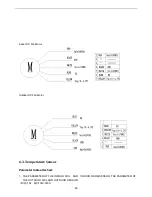
Page 39: ...39 AS 18UR4SFATDi6 AS 24UR4SDBTDI6 1 Terminal of DC fan 5 Terminal of compressor overload protector 9 Terminal of communication wire with filter board 14 Terminal of compressor W phase...

Page 40: ...neutral wire with filter board 16 Terminal of compressor U phase 4 Outdoor ambient temperature sensor 8 Terminal of AC fan 12 13 Terminal of reactor AS 18UR4SFATDI6 AS 24UR4SDBTDI6 1 Terminal of live...

Page 41: ...3 Terminal of communication wire connect to the driver board 6 Terminal of neutral wire connect to the terminal panel 1 N 41...

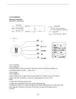
Page 42: ...ert screwdriver into to rotate indoor fan motor slowly for 1 revolution or over and measure voltage YELLOW and GND on motor The voltage repeat 0V DC and 5V DC Notes 1 Please don t hold motor by lead w...

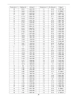
Page 43: ...Fan Motor Outdoor DC Fan Motor 6 3 Temperature Sensor Parameter table attached 1 THE PARAMETER OF THE INDOOR COIL AND INDOOR ROOM SENSOR THE PARAMETER OF THE OUTDOOR COIL AND OUTDOOR SENSOR R 0 15k B...

Page 44: ...7766 1 15 683 1 22696435 50 2 211 3 487894953 0 15 1 26865672 51 2 139 3 522585993 1 14 351 1 31098658 52 2 07 3 556485356 2 13 734 1 35393437 53 2 003 3 590032381 3 13 148 1 39741342 54 1 939 3 62267...

Page 45: ...38 59 14 684 1 582573078 11 330 048 0 10093573 60 14 151 1 622834232 10 312 904 0 10634837 61 13 64 1 663405088 9 296 761 0 11200385 62 13 151 1 704175229 8 281 556 0 11790981 63 12 682 1 745200698 7...

Page 46: ...31 44 537 0 66229036 102 3 602 3 268602192 32 42 676 0 68720188 103 3 501 3 300650422 33 40 904 0 71272849 104 3 409 3 33039475 34 39 217 0 73885738 105 3 317 3 360680043 35 37 609 0 76561057 106 3 22...

Page 47: ...normality Notes 1 Don t put a compressor on its side or turn over 2 Please assembly the compressor in your air conditioner rapidly after removing the plugs Don t place the comp In air for along time 3...

Page 48: ...erature sensor is failure c the outdoor control board is failure Communication failure between the indoor unit and outdoor unit a the communication cable connect loose b the communication cable is fai...

Page 49: ...eze protection with cooling or overload protection with heating in indoor unit a the indoor coil temperature sensor connect loose b the indoor coil temperature sensor is failure c the indoor control b...

Page 50: ...perature too low Mark description the lights flash every two seconds for the following faults Protection against overheated outdoor radiator a Radiator sensors fail b Detection circuit of the sensor o...

Page 51: ...display when the communication between display board and control board have in trouble a The connection between the display board and control board is loose b The indoor control board is failure c The...

Page 52: ...unit has been installed without standard 6 AC voltage higher or lower protection a the supply voltage is higher or lower than normal b the inner supply voltage of the unit is higher or lower than norm...

Page 53: ...exhaust temperature too high protection a the compressor exhaust temperature sensor is failure b the refrigerant of the unit is not enough 14 Outdoor ambient temperature sensor in trouble a the outdoo...

Page 54: ...motor is failure c the outdoor fan is broken d the condensor is dirty e the air inlet and air outlet of the indoor unit and the outdoor unit is not normally 22 Compressor pre heating process it is no...

Page 55: ...board is failure g the power board is failure h the outdoor control board is failure 38 o Indoor EEPROM failure a The EEPROM chip loose b The indoor control board is failure 39 o x Indoor fan motor r...

Page 56: ...oor unit and outdoor unit a the communication cable connect loose b the communication cable is failure c the connection between the filter board and the outdoor control board is incorrect or loose d t...

Page 57: ...he compressor exhaust temperature sensor connect loose b the refrigerant of the unit is not enough 16 x Anti freeze protection with cooling or overload protection with heating in a the indoor coil tem...

Page 58: ...ssure detection switch on the control panel fails c The measured value of system pressure exceeds the limit 33 The failure for temperature sensor of indoor room d The indoor room temperature sensor lo...

Page 59: ...le out the communications failures adopt screening method such as short circuit on the jumper terminals to see if the external unit can be started normally or similar method There are two blue termina...

Page 60: ...igeration current protection E2 value over current protection will be released 2 Frequency decreasing for over current Conditions for over current frequency decreasing if the current is equal to or gr...

Page 61: ...d 7 4 Trouble Diagnosis of Compressor Judging the connecting terminals of inverter compressor It is impossible to identify terminals U V and W of inverter compressor with multi meter Just connect the...

Reviews: