background image

5

5

.

.


C

C

O

O

N

N

T

T

R

R

O

O

L

L


M

M

O

O

D

D

E

E


A

A

S

S

-

-

1

1

8

8

U

U

R

R

4

4

S

S

T

T

V

V

U

U

H

H

1

1


16

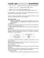
T

set

-T

room


Indoor Fan Speed 

T

set

-T

room

2

0

C Low 

2

0

<

T

set

-T

room

<

4

0

C Medium 

T

set

-T

room

4

0

C High 

 
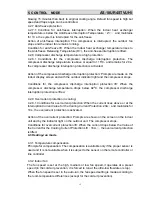
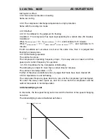
4.3.3 Cold air prevention 
In the heating-run, to prevent the indoor fan from blowing cold air, the indoor fan 
speed is controlled as illustrated below: 


            35℃     Set fan speed    

Down

   Set fan speed                       Up   

              30℃   low fan speed 
     ultra-low speed 
              25℃     stop 
              stop 


4.3.4 Residual heat blowing off 
When the compressor is turned off in the heating run, the indoor fan does not stop at 
once, continue running for 30 seconds at last. 
4.3.5 Outdoor fan 
The outdoor fan speeds are divided into three levels which can be changed over 
according to outdoor ambient temperatures. 
4.3.6 4-way valve 
State: It is electrified in heating. 
Switchover: When initially powered on for heating, the 4-way valve is activated 
immediately. 
 
In the change from cooling to heating, it needs an interval of 50 seconds for the 
4-way valve to change over from being interrupted to being activated.     
 
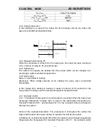
4.3.7 Overload control 
4.3.7.1 Conditions for the system to be interrupted on overload: When the indoor heat 
exchanger temperature is higher than or equal to the Interrupting Temperature for 
Overload Protection 65

, and maintains for 10 s, the overload control is activated to 

interrupt the system. 
 

Action of the overload interruption: The compressor is interrupted, the outdoor fan 
stops and the indoor fan keeps running or operates for cold air prevention. 

Conditions for overload interruption lift: When the indoor heat exchanger temperature 
drops below the Temperature for Overload Protection Lift 47

, the overload control 

Summary of Contents for AS-18UR4STVUH1

Page 1: ...AS 18UR4STVUH1...

Page 2: ...Type of contents 1 OPERATION RANGE 1 2 SPECIFICATION 2 3 INSTALLATION 6 4 ELECTRICAL DATA 7 5 CONTROL MODE 13 6 TROUBLE SHOOTING 20 7 CHECKING COMPONENTS 25 8 PARTLIST 28...

Page 3: ...1 18 8U UR R4 4S ST TV VU UH H1 1 1 Temperature Indoor Air Intake Temp Outdoor Air Intake Temp Maximum 32 D B 23 W B 43 D B 26 W B COOLING Minimum 21 D B 15 W B 21 D B 15 W B Maximum 27 D B 18 W B 24...

Page 4: ...nt charge volume g 1700 High dB A 48 Indoor Unit Noise Level Low dB A 40 Outdoor Unit Noise Level dB A 58 Power Supply Voltage Frequency Phase V 220 240V 50Hz 1P Cooling A 7 6 Rated Current Heating A...

Page 5: ...CE WEEE RoHS NOTE Test conditions Cooling Indoor DB27 WB19 Outdoor DB35 WB24 Heating Indoor DB20 WB15 Outdoor DB7 WB 6 2 2 Major component specifications 2 2 1 INDOOR FAN MOTOR WIRING DIAGRAM ELECTRIC...

Page 6: ...4 Rated load output W 36W Ambient temperature 5 43 WIRING DIAGRAM 2 2 3 COMPRESSOR ELECTRIC PERFORMANCE PARAMETER Compressor model DA130S1C 20FZ Compressor type Rotary DC inverter Motor type DC Brush...

Page 7: ...omponent specifications 2 3 1 STEPPER MOTOR ELECTRIC PERFORMANCE PARAMETER Stepper Motor model DG13B1 01 Voltage DC 12V Number of phase 4 Drive mode 1 2 phase excitation unipolar drive Resistance per...

Page 8: ...n air outlet of outdoor unit and the opposite object should be more than 1 meter otherwise the machine would stop running because of overload by heat yield failure If the outdoor unit was opposite the...

Page 9: ...4 4 E EL LE EC CT TR RI IC CA AL L D DA AT TA A A AS S 1 18 8U UR R4 4S ST TV VU UH H1 1 7 4 1 Electrical wiring diagrams 4 1 1 INDOOR...

Page 10: ...DOOR CN703 W U CN1 CN102 CN801 V CN4 CN3 U R V S W C BK BK WH BK BU BN YE GN FILTER CN203 CN202 BU BU FAN MOTER CN11 L1 CN12 L2 CN13 CAP BK GY CN10 BN CN7 CN6 YE GN CN704 CN702 CN701 N RD BU BU BN CN6...

Page 11: ...0 DC 6 253 9 0 3651 19 13 50 20 79 2 4516 125 7D 106 3 059 4 3367 221 DD 5 241 1 0 3830 20 14 51 20 01 2 4994 127 7F 107 2 97 4 3535 222 DE 4 229 0 4016 20 14 52 19 26 2 5471 130 82 108 2 884 4 3699 2...

Page 12: ...265 2 9504 150 96 86 0 725 4 3318 221 DD 9 22 82 0 8539 44 2C 39 3 151 2 9932 153 99 87 0 7053 4 3476 222 DE 8 21 75 0 8885 45 2D 40 3 041 3 0358 155 9B 88 0 6861 4 3631 223 DF 7 20 74 0 9237 47 2F 41...

Page 13: ...3 73126 114 2 56 29 0 3853091 19 650762 20 48 5 608 2 2797827 116 26892 116 1 53 41 0 4044054 20 624677 21 49 5 387 2 3297313 118 8163 119 0 50 69 0 4242643 21 63748 22 50 5 177 2 379265 121 34251 121...

Page 14: ...174 24 15 7 1 1519608 58 75 59 74 2 114 3 4487819 175 88788 176 25 15 1 1928934 60 837563 61 75 2 041 3 4861297 177 79261 178 26 14 33 1 2348923 62 979506 63 76 1 971 3 5227102 179 65822 180 27 13 7 1...

Page 15: ...ording to the data from the remote controller 2 Temperature the setting temperature value is displayed according to the data from the remote controller is displayed when dehumidifying mode and air blo...

Page 16: ...can be changed over according to outdoor ambient temperatures When operating at a fixed frequency the outdoor fan is forced to operate at the high speed 4 2 3 Indoor fan When the fan speed is set at t...

Page 17: ...sor stops Conditions for the compressor discharge interruption protection lift When the compressor discharge temperature drops below 920 C the compressor discharge interruption protection is lifted 4...

Page 18: ...es 4 3 6 4 way valve State It is electrified in heating Switchover When initially powered on for heating the 4 way valve is activated immediately In the change from cooling to heating it needs an inte...

Page 19: ...osting has taken place 4 3 10 2 Defrosting operation The outdoor fan stops The compressor s operating frequency drops the 4 way valve is closed and then goes up at a certain frequency for operation 4...

Page 20: ...t does not work while the indoor fan runs with the fan speed selectable at the auto low medium and high speeds When being auto the fan speed is determined in the cooling mode The high medium and low f...

Page 21: ...requency 8 Communication frequency drops 4 7 Special notes 4 7 1 The indoor unit of this model is electrified by the outdoor unit After the system starts to operate the outdoor unit supplies the indoo...

Page 22: ...cuited or the corresponding test circuit in trouble 6 Outdoor atmosphere temperature sensor short circuited open circuited or the corresponding test circuit in trouble 7 Signal communication abnormal...

Page 23: ...r in trouble 8 Current overload control 36 Communication between the indoor and outdoor in trouble 9 Maximum current control 39 Indoor fan motor operation abnormal 10 4 way valve changeover abnormal 4...

Page 24: ...l board Display board trouble Indoor control board is faulty Replace it No Does it receive the remote controller signal Yes Start up self test function Is the remote controller in good condition Check...

Page 25: ...eplace it Error code 34 Indoor Coil sensor trouble Error code 33 Indoor temperature sensor Does the resistance of thermistor have the characteristics Does the unit exit hot protector Replace the therm...

Page 26: ...remote controller Check the connector of indoor motor Does the socket CN1 1 3 of indoor control board have power input Indoor control board faulty and replace it Is resistance of main winding 0 short...

Page 27: ...t Is there power output between 1 and 2 on terminal block of indoor unit Is there power output AC220V of indoor unit between N out and L out Indoor control board and replace it Is the system in good c...

Page 28: ...Please don t plug IN OUT the motor connector while power ON 3 Please don t drop Hurl or dump motor against hard material Malfunction may not be observed at early stage after such shock But it may be...

Page 29: ...stance TOOL Multimeter Test the resistance of the winding The compressor is fault if the resistance of winding 0 short circuit or open circuit Familiar trouble 1 Compressor motor lock 2 Discharge pres...

Page 30: ...pen circuit 6 STEPPER MOTOR Resistance per phase 200 7 3 yellow 1 blue 5 red M Test in resistance TOOL Multimeter Test the resistance of winding The stepper motor is fault if the resistance of winding...

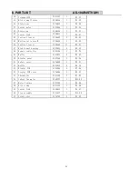
Page 31: ...8 3 Filter 1248291 1 1 31 4 Cabinet 1248291 1 1 31 5 Evaporator assembly 1311414 2 35 84 6 Bearing 1223738 2 0 44 7 Indoor fan 1247788 1 5 96 8 Chassis 1246139 1 7 54 9 Installation plate 1248081 1 2...

Page 32: ...8648 1 2 00 26 Vertical louver 1248650 11 0 03 27 Wind tunnel bearing 1222824 3 0 12 28 Remote controller 1222186 1 3 74 29 Baffle 1223851 2 0 02 30 Display panel 1247269 1 0 26 31 Safety cover 127659...

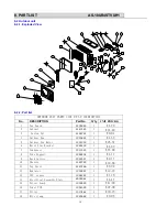
Page 33: ...1276849 1 4 79 2 Cabinet 1247465 1 14 40 3 Fasten Nut 1226724 1 0 04 4 Outdoor Fan 1313822 1 4 53 5 Outdoor Fan Motor 1331300 1 26 57 6 Motor Stay Bracket 1248203 1 4 69 7 Condenser 1311325 1 78 00 8...

Page 34: ...ate 1248048 1 1 71 29 Right Side Plate 1246297 1 4 00 30a 4 Way Valve Assembly 1354622 1 29 00 30b 4 Way Valve Coil 1202908 1 4 37 31 Noise insulation cotton 8007984 1 1 72 32 Compressor 1341332 1 120...

Reviews: