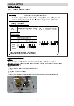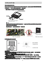
In case of using or cancelling the access control / fire protection function, use the wired controller to
modify the parameters of indoor unit.
NOTE: please refer to “ Indoor unit parameter revision ” section in TC Manual for how to use the
wired controller to modify the parameters of indoor unit.
(1) Access control: control mode to control the unit startup & shutdown based on the ON & OFF state
of the access control port.
(2) Fire protection: control mode to control the unit startup & shutdown based on the ON & OFF state
of the fire protection port.
10
.
2
.3 Function setting
(
1
)
Hardware
connection
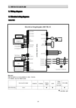
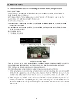
Figure 1 electrical wiring diagram
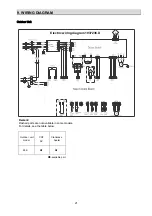
Figure 2 short wiring
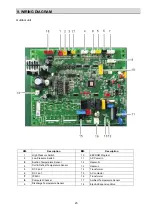
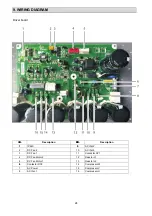
Figure 3 main control board
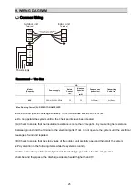
3 pins of the OUT INPUT CN16 socket shown in the electrical wiring diagram of Figure 1 are short
circuited state under as factory default (an external short circuit plug shown as Figure 2, and the OUT
INPUT CN16 socket of main control board is shown as Figure 3).
(Illustration: the socket number in circuit is subject to the actual serial number of PCB.)
1)
When using the door lock function, the red wire should be cut and connect the door lock control switch
attached to it (supplied by user), and the connecting wire should be 22AWG or above. In normal
conditions, the unit operates normally once the switch is closed and shuts down once the switch is off.
2) When using the fire protection function, the red wire should be cut and connect the fire protection lock
control switch attached to it (supplied by the user), and the connecting wire should be 22AWG or above.
In normal conditions, the unit operates normally once the switch is closed and shuts down once the
switch is off.
10.2 Instructions for the function setting of access control, fire protection
10.2.1 Factory setting
10.2.2 Function introduction
10.FIELD SETTING
34

