background image

Product improvement, specifications and appearance in this manual are subject to change without prior notice.

Summary of Contents for AUF-48UR6RTMPA

Page 1: ...TECHNICAL SERVICE MANUAL V1 0 DC INVERTER AIR CONDITIONERS MODEL AUF 48UR6RTMPA R32 Refrigerant...

Page 2: ...etting 27 10 1 Outdoor unit DIP switch 27 10 2 Instructions for the function setting of access control fire protection 34 11 Piping work and refrigerant charge 36 11 1 MAX length allowed 36 11 2 Oil t...

Page 3: ...ting Methods The refrigerant pipe can be connected from 3 different directions rear right or left More methods more conveniently Self Recovery of Power Break When the power supply is recovered after b...

Page 4: ...ilable model 1 GENERAL 42K 48K 60K Floor standing Model Btu h Type 1 3 Nomenclature 48 1 4 Unit installation 1 1 system is the only compatible combination One indoor unit can only be connected with on...

Page 5: ...e condition Temperature 20 65 Humidity 30 80 1 GENERAL Working Voltage Voltage Imbalance Within a 3 deviation from each voltage at the main terminal of outdoor unit Starting Voltage Higher than 85 of...

Page 6: ...1 6 Product picture Model capacity 48K Indoor Unit Outdoor Unit 1 GENERAL 4...

Page 7: ...nce 4 FAN SPEED BUTTON For selecting indoor fan speed Each time FAN button is pressed the fan speed is changed in sequence It can also be used to unlock the user interface The user interface will lock...

Page 8: ...or set temperature default display indoor set temperature 7 Heater display It lights up during heating mode when electric heater is on Only valid for models with electric heater 8 9 10 11 Fan speed se...

Page 9: ...W W 3 36 Indoor fan motor Model ZW702B500008 Qty 1 Output W 200 Speed Hi Med Lo r min 500 450 410 Indoor coil Number of rows 3 Tube pitch a x Row pitch b mm 21x18 19 Fin spacing mm 1 4 Fin type Hydro...

Page 10: ...40 HQ 26 53 106 Design pressure H L MPa 4 3 1 6 Refrigerant piping Liquid Gas mm inch 9 52 19 05 3 8 3 4 Pipe length Max m 50 Height difference Max OD lower m 30 Max OD higher m 30 Add Refrigerant Amo...

Page 11: ...3 Outlines and dimensions 3 1 Indoor unit 3 OUTLINES AND DIMENSIONS Unit mm 9...

Page 12: ...3 2 Outdoor unit Unit mm 3 OUTLINES AND DIMENSIONS 10...

Page 13: ...y 2 This data is based on the same conditions as the nominal heating and cooling capacities 3 The compressor is started by an inverter resulting in extremely low starting current Outdoor unit Power su...

Page 14: ...re WB Wet Bulb Temperature Outdoor temperature DB Indoor temperature WB DB 20 25 32 35 40 45 14 20 11 1 10 9 10 1 9 9 9 1 8 6 16 22 12 1 11 6 11 4 10 6 9 9 9 4 18 25 12 6 12 1 12 4 11 6 11 1 10 6 19 2...

Page 15: ...gher than position of indoor unit m H 0 Position of outdoor unit is lower than position of indoor unit m L Actual one way piping length between indoor unit and outdoor unit m EL Equivalent one way pip...

Page 16: ...the outdoor unit is installed higher or lower than the indoor unit it is necessary to apply height correction factor additionally to length correction factor to calculate cooling heating If outdoor un...

Page 17: ...Corre ection factor r x unit capacity The heating capacity in the previous paragraph is given without consideration of the condition of defrosting operation period In consideration of defrosting opera...

Page 18: ...0 63 125 250 500 1k 2k 4k 8k Total octave band sound level dB total sound level C Octave band center frequency Hz Model 48K Test condition 1 0m under the unit 1 0m high from the ground 0 10 20 30 40 5...

Page 19: ...Air flow distribution Floor standing installation Cooling Air Velocity Distribution Floor standing installation Cooling Air Temperature Distribution 7 AIR FLOW DISTRIBUTION 7 1 2 17...

Page 20: ...t cycle Indoor Unit 2 1 1 3 5 4 Cooling Cycle Heating cycle List of components 1 Hexagon nut 4 Ambient temperature sensor 2 Split capillary 5 Coil temperature sensor 3 Indoor heat exchanger 8 REFRIGER...

Page 21: ...sor 8 Defrost temperature sensor 2 Low pressure switch 9 Coil temperature sensor 3 High pressure switch 10 Ambient temperature sensor 4 Discharge temperature sensor 11 Electronic expansion valve 5 Suc...

Page 22: ...ashed parts are not available in some models For details see the table below available part Indoor units model Humidity WIFI NANOE Display board Wired remote controller 48K YEL GRN Floor standing 9 WI...

Page 23: ...For details see the table below Outdoor unit model CN7 48K available part Crankcase SV heater 1 2 1 2 1 2 1 2 1 2 1 2 1 2 1 2 1 2 1 2 M L1 L2 L3 N E N L3 L2 L1 E M 1 2 1 2 1 2 1 2 1 2 1 2 1 2 1 2 1 2...

Page 24: ...ndoor unit O Description NO NO NO Description 1 1 Swing 8 8 Display 2 2 L IN 9 9 Room N IN 3 3 10 Coil 4 4 SI IN 11 WIFI Output 5 5 12 EE Prom 6 6 Nano 13 Fan Motor 7 7 Step Motor 9 WIRING DIAGRAM 22...

Page 25: ...AC Power in 3 3 Suction Temperature Sensor 12 Heater N 4 Coil Defrost Temperature Sensor 13 Heater L 5 DC Fan 2 14 Transformer 6 DC Fan 1 15 AC contactor IPM SI 7 7 16 Transformer 8 8 Computer Checke...

Page 26: ...O 1 1 IPM S 9 9 AC IN L2 2 DC Fan 2 10 AC IN L3 3 DC Fan 1 11 Contactor RY1 4 DC Fan Motor 2 12 Reactor L1 5 DC Fan Motor 1 13 Reactor L2 6 6 Contactor RY2 14 Compressor W 7 AC Power 15 Compressor V 8...

Page 27: ...oor unit are fully open and then start the system Pay attention to the following items while the system is running A Do not touch any of the parts by hand at the discharge gas side since the compresso...

Page 28: ...ubber sheathed flexible cord code designation H07RN F or ordinary polychloroprene sheathed flexible cord code designation H07RN F 3 Use a shielded cable for the transmitting circuit and connect it to...

Page 29: ...uired Refrigerantc ollection mode Actions The compressor runs with the aim frequency and without any protection when raise frequency The EEV runs with setting opening Outdoor unit fan will run with th...

Page 30: ...it count down to 0 40 39 38 0 and 0 begins to blink close the shut off valve of the gas piping with an Allen wrench in a clockwise direction Step 9 Cut off machine power and the procedure for recoveri...

Page 31: ...number blink at the same time Press button to adjust parameter number until 17 is displayed stops blinking And press ENTER button to enter system parameter adaption state symbol parameter number blin...

Page 32: ...emperature sensor Integer 0 0 1 0 5 2 1 3 1 5 4 2 5 2 5 6 3 7 3 5 8 4 9 4 5 10 5 the wired controller displays integer with the symbol 9 Heating Temperature Compensation indoor unit temperature sensor...

Page 33: ...or unit air inlet temperature 07 Indoor unit coil sensor temperature 08 Outdoor unit ambient sensor temperature 09 Discharge temperature 10 Suction temperature 11 Outdoor coil temperature 12 Discharge...

Page 34: ...TCH button Indoor parameters and outdoor parameters can be selected in turn by pressing it P outdoor unit parameter H indoor unit parameter 2 INCREASE button Each time it is pressed the number rises b...

Page 35: ...or EEV Opening P 5 Outdoor EEV Target Opening P 6 Upper DC Motor Revolving Speed P 8 AC Input Voltage P 9 Current P 10 Modular Temperature P 11 Capacity Needed P 12 Modular Fault P 20 Outdoor Ambient...

Page 36: ...tory default an external short circuit plug shown as Figure 2 and the OUT INPUT CN16 socket of main control board is shown as Figure 3 Illustration the socket number in circuit is subject to the actua...

Page 37: ...ff and the startup shutdown control is enabled Fire protection 1 Access to fire protection the air conditioner will be shut down and won t blow air after the access control signal is disconnected for...

Page 38: ...ength m 48K 50 30 Oil trap Slope 1 200 1 250 Slope 1 200 1 250 11 PIPING WORK AND REFRIGERANT CHARGE When the indoor unit is lower than outdoor unit and height difference is larger than 5m install an...

Page 39: ...trogen when performe air tight test Connect the gauge manifold using charging hoses with a nitrogen cylinder to the check joints of the liquid line and the gas line stop valves Perform the air tight t...

Page 40: ...es Torque Wrench or 1 2 5 8 spanner size is up 2mm Connection of Flare Nut Fo 1 4 3 8 3 4 spanner size is the same Brazing Tool Perform correct brazing work Brazing for Tubes Nitrogen Gas Strict Contr...

Page 41: ...unit and outdoor unit Indoor unit installation Electrical wiring Drain piping installation Duct installation Refrigerant piping installation Heat insultation Outdoor unit installation Vacuum pumping...

Page 42: ...in the preset conditions after receiving a signal from the remote controller If the air conditioner has not received a signal from the remote controller when the set time is up it will automatically...

Page 43: ...or turn off mute function with mute key The air conditioner will run with mute fan speed in mute mode 2 6 Cooling wind prevention mode In the heating run to prevent the indoor fan from blowing cold ai...

Page 44: ...he indoor panel 2 11 Filter cleaning Filter cleaning LED will light up when air filter is clogged with dust How to set cancel It can be set cancelled with the wired remote controller For details see i...

Page 45: ...come to automatic protection mode 4 Oil return Control When the compressor runs at low frequency for a long time thecontrol system will start the oil return mechanism The oil in the system returns to...

Page 46: ...3 5903 314 9620 336 5448 6 79 6 41 9 278 4719 298 5822 318 3744 6 74 6 22 8 264 2156 283 1464 302 2294 6 69 6 31 7 250 7678 268 5936 286 5448 6 64 6 26 6 238 0783 254 8686 271 7603 6 59 6 22 5 226 100...

Page 47: ...36 4 15 46 23 0530 24 0950 25 1293 4 32 4 12 47 22 1757 23 1688 24 1545 4 29 4 08 48 21 3360 22 2826 23 2221 4 25 4 05 49 20 5321 21 4345 22 3301 4 21 4 01 50 19 7623 20 6226 21 4766 4 17 3 98 51 19 0...

Page 48: ...53 2 47 102 3 4601 3 5509 3 6419 2 56 2 50 103 3 3577 3 4468 3 5362 2 59 2 53 104 3 2588 3 3463 3 4341 2 61 2 56 105 3 1632 3 2491 3 3353 2 64 2 58 106 3 0708 3 1551 3 2398 2 67 2 61 107 2 9816 3 064...

Page 49: ...97 30 89 3 00 2 98 14 27 73 28 56 29 39 2 91 2 82 13 26 46 27 22 27 98 2 79 2 72 12 25 26 25 95 26 64 2 66 2 59 11 24 11 24 75 25 38 2 59 2 48 10 23 03 23 61 24 19 2 46 2 40 9 21 99 22 53 23 06 2 40 2...

Page 50: ...924 4 24 4 20 30 4 355 4 550 4 753 4 29 4 27 31 4 198 4 390 4 589 4 37 4 34 32 4 048 4 236 4 431 4 44 4 40 33 3 904 4 089 4 280 4 52 4 46 34 3 766 3 946 4 134 4 56 4 55 35 3 663 3 810 3 994 3 86 4 61...

Page 51: ...53 7 02 6 94 75 0 9676 1 041 1 120 7 05 7 05 76 0 9385 1 011 1 088 7 17 7 08 77 0 9104 0 9810 1 056 7 20 7 10 78 0 8833 0 9523 1 026 7 25 7 18 79 0 8570 0 9246 0 9971 7 31 7 27 80 0 8316 0 8977 0 9687...

Page 52: ...66 107 0 3841 0 4210 0 4611 8 76 8 70 108 0 3739 0 4100 0 4493 8 80 8 75 109 0 3640 0 3993 0 4379 8 84 8 81 110 0 3544 0 3890 0 4267 8 89 8 84 111 0 3450 0 3789 0 4159 8 95 8 90 112 0 3360 0 3692 0 40...

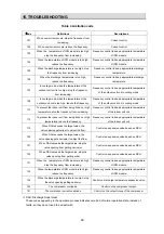
Page 53: ...3 Check if there is a defective contact or leak current in the power supply circuit 4 Check and set remote controller again 5 Replace batteries The compressor starts or stops frequently The air inlet...

Page 54: ...Outdoor Unit Fault code will display on digital tube board 7 segment display Outdoor Control Board 15 TROUBLESHOOTING 52...

Page 55: ...ction cable referring to the wiring diagram 2 Reconnect the communication cable 3 Replace the communication cable 4 Replace the indoor control board 5 Replace the outdoor control board 6 Check the com...

Page 56: ...he wiring of the defrosting sensor 2 Replace the defrosting sensor 3 Replace the outdoor control board 45 IPM fault There are many reasons for this failure You can check the driver board fault LED to...

Page 57: ...ard F0 240 Wired remote controller EEPROM failure 1 EE of wired remote controller is abnormal 2 The control board of the wired remote controller is abnormal Change the wired remote controller F1 241 W...

Page 58: ...Check the outdoor fan motor and fan capacitor 6 The outdoor fan is broken or the outdoor fan is blocked Check the outdoor fan 7 The air inlet and outlet has been blocked Remove the obstacles 8 The exp...

Page 59: ...s in the air outlet and air inlet of the outdoor unit Adjust the installation of the indoor unit referring to the user manual 4 The indoor filter is dirty Clean the indoor filter 5 The speed of the in...

Page 60: ...ge overload voltage 1 Supply voltage input is too high 2 Driver board fault 1 Check power supply 2 Change the driver board 9 AC voltage imbalance Driver board fails Change the driver board 10 The PFC...

Page 61: ...EE data error 1 EEPROM has no data or data error 2 EEPROM circuit fault 1 Change EEPROM component 2 Change the driver board 19 PFC chip receive data fault Abnormal communication loop Change the drive...

Page 62: ...ep appropriate temperature of the indoor unit coil 114 To prevent the indoor unit from being frozen or high temperature reduce the frequency Frequency control to keep appropriate temperature of the in...

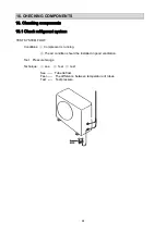
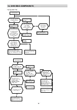
Page 63: ...SYSTEM FLOW Conditions Compressor is running The air condition should be installed in good ventilation Tool Pressure Gauge Technique see feel test See Tube defrost Feel The difference between temperat...

Page 64: ...e to static pressure NO NO 4 way valve collude or compressor exhaust very ebb yes NO yes Heating mode Test system pressure Is the high pressure normal at service part The pressure on the high side The...

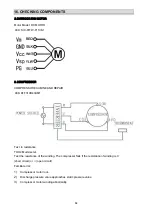
Page 65: ...age TOOL Multimeter Insert screwdriver to rotate indoor fan motor slowly for 1 revolution or over and measure voltage YELLOW and GND on motor The voltage repeats 0V DC and 5V DC NOTES NO Please don t...

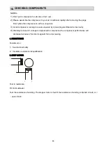
Page 66: ...CHECKING COMPONENTS 16 Test in resistance TOOL Multi meter Test the resistance of the winding The compressor fails if the resistance of winding is 0 short circuit or open circuit Familiar error 1 Com...

Page 67: ...ircuit NOTES 1 Don t put a compressor on its side or turn over 2 Please assemble the compressor in your air conditioner rapidly after removing the plugs Don t place the compressor in air for a long ti...

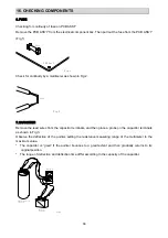
Page 68: ...terminals and then place a probe on the capacitor terminals as shown in Fig 3 Observe the deflection of the pointer setting the resistance measuring range of the multimeter to the maximum value The c...

Page 69: ...ve the blade nut then remove the blade 2 Remove the motor from the motor supporter 3 Remove the compressor 1 Unsolder the 4 way valve piping assy from the compressor 2 Remove the compressor mounting b...

Page 70: ...ction 1 Remove the screws Remove the four screws at the left and right air inlets 2 Rotate the level vanes Rotate the level vanes parallel to the direction of the wind 3 Remove the panel parts Panel P...

Page 71: ...on the front of air inlet parts 5 Remove the fan 1 Remove the air guiding plate by rotating it clockwise 2 Unscrew the hex nuts 3 Remove the centrifugal fan 6 Remove the motor 1 Unscrew the hex nuts...

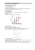
Page 72: ...compressor starts up it will follow the below rules When indoor room temp T1 is lower than Ts the compressor and outdoor fan will shut off When T1 is higher than Ts 1 the compressor and outdoor fan wi...

Page 73: ...The auto fan T1 is indoor room temperature Ts is setting temperature DC Inverter outdoor unit Outdoor fan running rules Once the outdoor fan starts up it will follow the below rules Single outdoor fan...

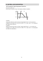
Page 74: ...me as in relevant mode If the compressor keep stopping for 10 minutes or the setting temperature is modified the machine will choose mode according to T again 18 5 Evaporator Low temperature Protectio...

Page 75: ...up Condition2 Heating mode When the indoor coil temp T3 keeps higher than T2 for 10 seconds the compressor and outdoor fan will shut off When T3 is lower than T1 the compressor and outdoor fan will re...

Page 76: ...Product improvement specifications and appearance in this manual are subject to change without prior notice...

Reviews: