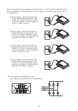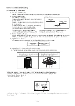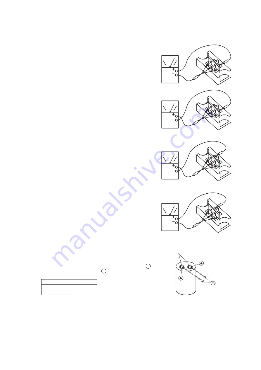
(a) By touching the + side of the tester to the +
terminal of diode module and the - side of tester
to the ~ terminals (3 NOs.) of the diode module,
measure the resistance. If all the resistances
are from 5 to 50kΩ, it is normal.
(b) By touching the - side of the tester to the +
terminal of diode module and the + side of tester
to the ~ terminals (3 NOs.) of the diode module,
measure the resistance. If all the resistances
are greater than 500kΩ, it is normal.
(c) By touching the - side of the tester to the -
terminal of diode module and the + side of tester
to the ~ terminals (3 NOs.) of the diode module,
measure the resistance. If all the resistances
are from 5 to 50kΩ, it is normal.
(d) By touching the + side of the tester to the -
terminal of diode module and the - side of tester
to the ~ terminals (3 NOs.) of the diode module,
measure the resistance. If all the resistances
are greater than 500kΩ, it is normal.
If items (a) to (d) are performing and the results are satisfactory, the diode module is normal. Measure it
under 1kΩ range of a tester. Do not use a digital tester.
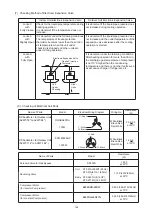
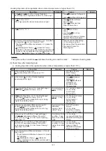
(4) Checking Method of Capacitor
(a) Check that the screws are connected tightly.
(b) Check that the capacitor is not tarnished or expanded.
* When checking the capacitor, disconnect the terminals
B
.
Do not disconnect the terminals
A
.
Screw
Capacitance
380-415V
For Inverter
4700
P
F
For Fan Controller
2700
P
F
137


