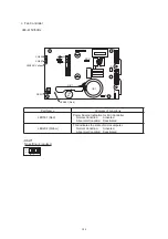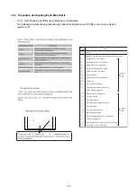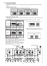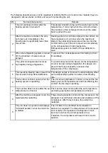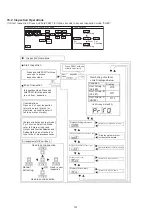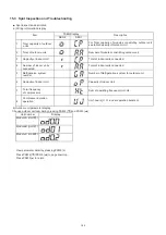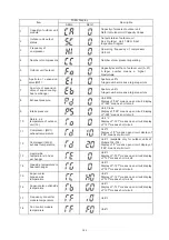
(6) Checking of Fan Controller
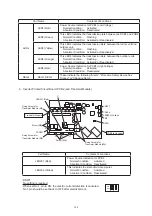
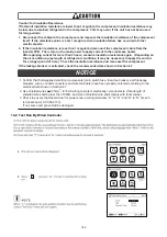
(a) Turn OFF the power source switches before this work.
Also ensure that LED501 (Red) on the fan controller is turned
OFF. If LED501 is ON, electrical shock may occur.
(b) Disconnect all the wirings connected to the fan controller.
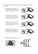
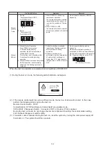
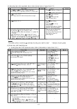
Measure the resistance between terminals using the tester. (Do not use a digital tester.)
When measuring, check the color of tester probe and the terminals to be measured as shown in the
table below.
Tester Probe
Red (+) - Black (-)
Resistance Range
P1
P1
P1
R
S
T
P1
P1
P1
U
V
W
-
-
-
-
-
-
-
-
-
-
-
-
R
S
T
N
N
N
U
V
W
N
N
N
1 kΩ and over
R
S
T
N
N
N
U
V
W
N
N
N
-
-
-
-
-
-
-
-
-
-
-
-
P1
P1
P1
R
S
T
P1
P1
P1
U
V
W
Resistance will gradually
increase once after it
is between 1700 kΩ to
1900 kΩ. ( )
(
)
Leave at least 30 seconds when measuring the next terminals.
Regarding DSW setting, do not change from the original setting. Abnormal transmitting and fan
controller failure may occur if the setting is changed.
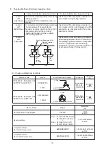
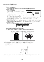
(5) Checking Method of Resistor
Measure the both ends of resistor as shown in the figure.
If the resistance is ∞Ω, it is abnormal.
Resistance
380-415V
For Inverter RS
-
RS1
0.5k
:
RS2
0.5k
:
R1
6.3k
:
R2
10.5k
:
N
S
R
V
U
LED501
LED
202
W
P1
138

