14. Test Run
●
Do not operate the system until all the check points have been cleared.
As for the test run of indoor unit, check “Installation & Maintenance Manual” attached to the indoor
unit and Switch Box.
14.1 Before Test Run
(1) Check to ensure that the refrigerant piping and transmission between outdoor unit and indoor units
are connected to the same refrigerant cycle. If not, it will cause an abnormal operation and a serious
accident.
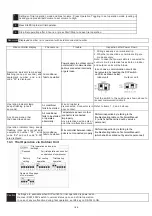
Check that the dip switch setting of the refrigerant cycle No. (DSW1 & RSW1 [O.U.], DSW5 & RSW2
[I.U.]) and the unit number (RSW) for the indoor units apply to the system.
Confirm that the dip switch setting on the printed circuit board of the indoor units and the outdoor units
are correct. Especially, pay attention to the setting of outdoor unit No., the refrigerant cycle No. and
the end terminal resistance. Refer to the chapter “7. Electrical Wiring”.
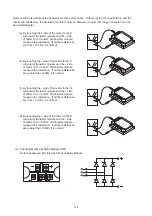
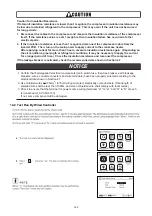
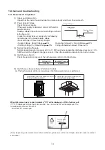
(2) Check to ensure that the electrical resistance is more than 1 megohm, by measuring the resistance
between ground and the terminal of the electrical parts. If not, do not operate the system until the
electrical leakage is found and repaired (Refer to “Caution for Insulation Resistance” for details.).
Do not impress the voltage on the terminals for transmission (Outdoor Unit: TB2 1, 2, 3, 4 /
Indoor Unit: TB2 1, 2, A, B / Switch Box: TB2 1, 2, 3, 4).
(3) Check to ensure that each wire, L1, L2, L3 and N is correctly connected at the power source.
If incorrectly connected, the unit will not operate and the remote control switch will indicate the alarm
code “05”. In this case, check and change the phase of the power source according to the attached
sheet on the reverse side of the service cover.
(4)
Check to ensure that the switch on the main power source has been ON for more than
12 hours, to warm the compressor oil by the oil heater.
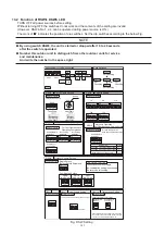
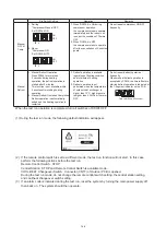
R series outdoor units does not operate within 4 hours after power supply (Stoppage Code d1-22).
In case of operating within 4 hours, release the protection control as follows:
1. Supply power to the outdoor unit.
2. Wait for 30 seconds.
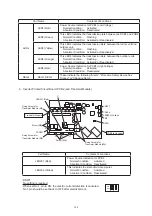
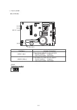
3. Push PSW5 on the outdoor PCB more than 3 seconds in order to release the d1-22.
In case of using remote control switch for release, push “Air Flow” and “Auto Louver” switch
simultaneously for 3 seconds.
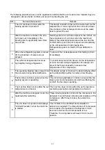
(5) Main Unit Label
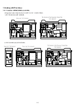
In case of the combination of base units,
attach the main unit label on a visible spot of the main
unit (outdoor unit A)
, so that the outdoor unit A can be identified easily. Do not attach the main label
on the sub unit (outdoor unit B and C).
141


