15.
4
.1 Initial Troubleshooting
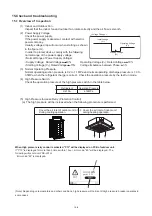
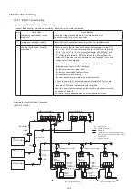
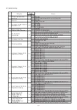
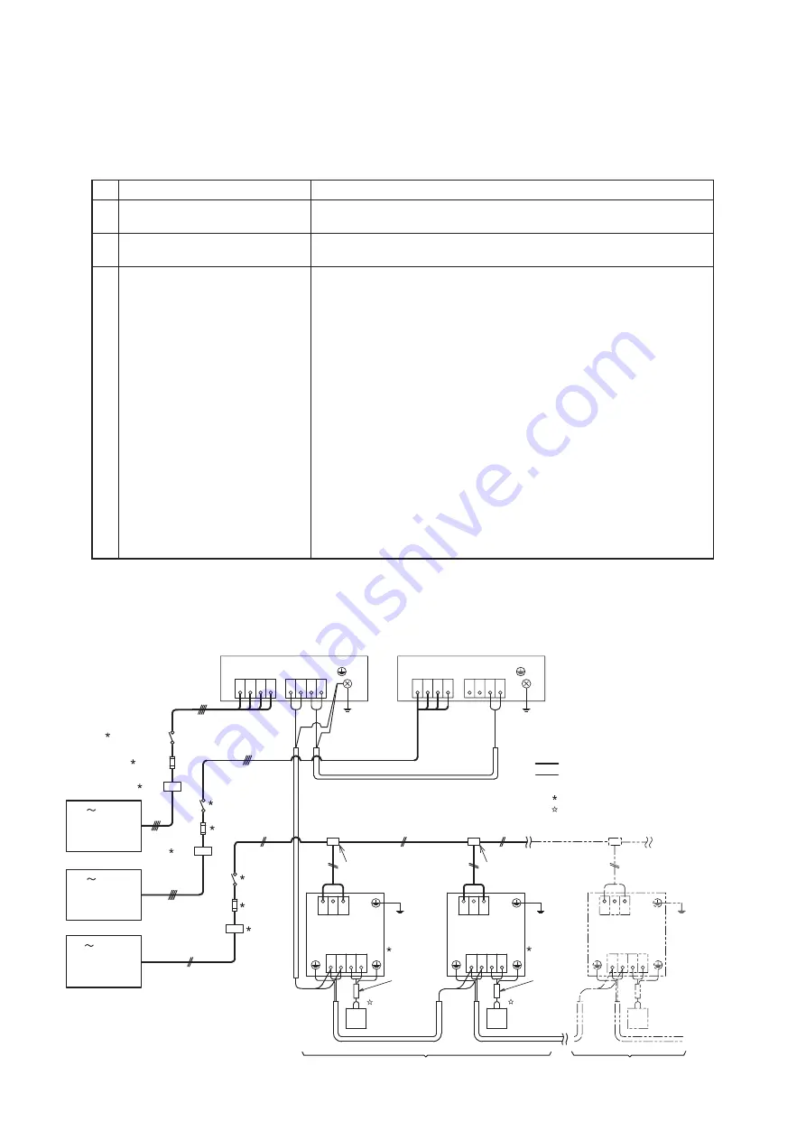
● Checking of Electrical Wiring and Power Source
Inspect the following items when abnormality is found during the system activation.
No.
Check Item
Check Method
1
Is power source breaker or fuse
blown out?
Check the voltage (secondary side) of the breaker and also
check the conductivity of fuse by a tester.
2
Is voltage at secondary side of
transformer correct?
Disconnect connection at the secondary side of the transformer and
measure voltage by a tester.
3 Is wiring firmly fixed or correctly
connected?
• Check to ensure that the terminal for power source wiring (terminals “L1”
to “L1” and “N” to “N” of each terminal board: AC380-415V, terminals
“R” to “L1” and “S” to “L2” of each terminal board: AC220-240V) and
intermediate wiring (Operating Line: terminals “1” to “1” and “2” to
“2” of each terminal board: DC5V) between the indoor unit and the
outdoor unit coincide correctly, as figure on the next page. If not, som
component will be damaged.
• Check the wiring connection to the PCB and especially ensure that the
following connections are NOT loosened.
(a) thermistor connector plug (each)
(b) remote control cable connector plug
(c) transformer connector plug
(d) each connector plug of main power source circuit
• Check to ensure that the twist pair cable with shield (≥0.75mm
2
) are
used for intermediate wiring to protect noise obstacle at total length of
less than 1000m and size complied with local code.
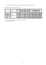
• Check to ensure that the wirings and the breakers are chosen correctly,
as shown in Table
15.4
.
• All the field wiring and equipment must comply with local code.
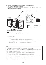
Example for Electrical Wiring Connection
< 380-415V/50Hz >
TB1
ELB
ELB
ELB
Main Switch
Main Switch
Main Switch
3N
380-415V/50Hz
1N
220-240V/50Hz
3N
380-415V/50Hz
TB1
TB2
L1 L2 L3 N
1 2 3 4
TB2
1 2 3 4
TB1
L1 L2 L3 N
1 2 A B
TB2
1 2 A B
TB2
TB1
L1 L2 N
L1 L2 N
No. 0
Indoor Unit
No. 1
Indoor Unit
Distribution Box or Pull Box
Distribution Box or Pull Box
FUSE
FUSE
FUSE
ELB
ELB
ELB
Outdoor Unit A (Main)
Earth
Earth
Outdoor Unit B (Sub)
Remote
Control
Cable
(Shielded Twist
Pair Cable)
Remote
Control
Cable
(Shielded Twist
Pair Cable)
Remote
Control
Switch
(HYXE-J01H)
Remote
Control
Switch
(HYXE-J01H)
No. 0 System Indoor Units
No.1 System Indoor Units
TB : Terminal Board
PCB : Printed Circuit Board
: Field Wiring
: Transmission Line (Shielded Twist Pair Cable)
DC5V (Non-Pole Transmission Hi-NET System)
: Field Supplied
: Optional Accessory
15.
4
Troubleshooting
162

